
RP2040-LCD-1.28
| ||

Overview
RP2040-LCD-1.28 is a low-cost, high-performance MCU board designed by Waveshare. Although it is tiny, it incorporates a 1.28inch LCD round display, Li-ion battery charger, 6-axis sensor (3-axis accelerometer and 3-axis gyroscope), and so on, adapting all GPIO and Debug headers, which makes it easy for you to develop and integrate it into products quickly.
Feature
- RP2040 MCU chip designed by Raspberry Pi in the United Kingdom.
- Dual-core Arm Cortex M0+ processor, flexible clock running up to 133 MHz.
- 264KB of SRAM, and 2MB of onboard Flash memory.
- Type-C connector, keeps it up to date, easier to use.
- Onboard 1.28inch LCD display.
- All GPIOs are adapted through 1.27 pitch female headers (There are 30 pins in total, but some pins have been connected to the internal circuit, you need to pay attention when multiplexing, please refer to the wiki for details).
- USB 1.1 with device and host support.
- Low-power sleep and dormant modes.
- Drag-and-drop programming using mass storage over USB.
- 2 x SPI, 2 x I2C, 2 x UART, 2 x UART, 4 x 12-bit ADC, 16 × controllable PWM channels.
- Accurate clock and timer on-chip.
- Temperature sensor.
- Accelerated floating-point libraries on-chip.
- 8 x Programmable I/O (PIO) state machines for custom peripheral support.
- Onboard Lithium battery recharge/discharge header, suitable for the RP2040-LCD-1.28 to be used in some mobile scenarios.
Specification
| LCD Parameter | |||
| Controller | GC9A01A | Resolution | 240 (H) RGB x 240(V) |
| Communication interface | SPI | Display Size | Φ32.4mm |
| Display Panel | IPS | Pixel Size | 0.135 (H) x 0.135 (V) mm |
| IMU Parameter | |||
| Sensor | QMI8658 | ||
| Accelerometer | Resolution: 16 bits Measurement Range (optional): ±2, ±4, ±8, ±16g | ||
| Gyroscope | Resolution: 16 bits Measurement Range (optional): ±16, ±32, ±64, ±128, ±256, ±512, ±1024, ±2048°/sec | ||
Pinout

Dimensions

Pico Getting Started
Firmware Download
- MicroPython Firmware Download

- C_Blink Firmware Download

Introduction
MicroPython Series
Install Thonny IDE
In order to facilitate the development of Pico/Pico2 boards using MicroPython on a computer, it is recommended to download the Thonny IDE
- Download Thonny IDE and follow the steps to install, the installation packages are all Windows versions, please refer to Thonny's official website for other versions
- After installation, the language and motherboard environment need to be configured for the first use. Since we are using Pico/Pico2, pay attention to selecting the Raspberry Pi option for the motherboard environment

- Configure MicroPython environment and choose Pico/Pico2 port
- Connect Pico/Pico2 to your computer first, and in the lower right corner of Thonny left-click on the configuration environment option --> select Configture interpreter
- In the pop-up window, select MicroPython (Raspberry Pi Pico), and choose the corresponding port


Flash Firmware
- Click OK to return to the Thonny main interface, download the corresponding firmware library and flash it to the device, and then click the Stop button to display the current environment in the Shell window
- Note: Flashing the Pico2 firmware provided by Micropython may cause the device to be unrecognized, please use the firmware below or in the package
- How to download the firmware library for Pico/Pico2 in windows: After holding down the BOOT button and connecting to the computer, release the BOOT button, a removable disk will appear on the computer, copy the firmware library into it
- How to download the firmware library for RP2040/RP2350 in windows: After connecting to the computer, press the BOOT key and the RESET key at the same time, release the RESET key first and then release the BOOT key, a removable disk will appear on the computer, copy the firmware library into it (you can also use the Pico/Pico2 method)

MicroPython Series
【MicroPython】 machine.Pin class function details
【MicroPython】machine.PWM class function details
【MicroPython】machine.ADC class function details
【MicroPython】machine.UART class function details
【MicroPython】machine.I2C class function details
【MicroPython】machine.SPI class function details
【MicroPython】rp2.StateMachine class function details
C/C++ Series
For C/C++, it is recommended to use Pico VS Code for development. This is a Microsoft Visual Studio Code extension designed to make it easier for you to create, develop, and debug projects for the Raspberry Pi Pico series development boards. No matter if you are a beginner or an experienced professional, this tool can assist you in developing Pico with confidence and ease. Here's how to install and use the extension.
- Official website tutorial: https://www.raspberrypi.com/news/pico-vscode-extension/
- This tutorial is suitable for Raspberry Pi Pico, Pico2 and the RP2040 and RP2350 series development boards developed by Waveshare
- The development environment defaults to Windows11. For other environments, please refer to the official tutorial for installation
Install VSCode
-
First, click to download pico-vscode package, unzip and open the package, double-click to install VSCode

Note: If vscode is installed, check if the version is v1.87.0 or later


Install Extension
-
Click Extensions and select Install from VSIX

-
Select the package with the vsix suffix and click Install

-
Then vscode will automatically install raspberry-pi-pico and its dependency extensions, you can click Refresh to check the installation progress

-
The text in the right lower corner shows that the installation is complete. Close VSCode


Configure Extension
-
Open directory C:\Users\username and copy the entire .pico-sdk to that directory

-
The copy is completed

-
Open vscode and configure the paths for the Raspberry Pi Pico extensions

The configuration is as follows:Cmake Path: ${HOME}/.pico-sdk/cmake/v3.28.6/bin/cmake.exe Git Path: ${HOME}/.pico-sdk/git/cmd/git.exe Ninja Path: ${HOME}/.pico-sdk/ninja/v1.12.1/ninja.exe Python3 Path: ${HOME}/.pico-sdk/python/3.12.1/python.exe


New Project
-
The configuration is complete, create a new project, enter the project name, select the path, and click Create to create the project
To test the official example, you can click on the Example next to the project name to select
-
The project is created successfully


Compile Project
-
Select the SDK version

-
Select Yes for advanced configuration

-
Choose the toolchain, 13.2.Rel1 is applicable for ARM cores, RISCV.13.3 is applicable for RISCV cores. You can select either based on your requirements

-
Select Default for CMake version (the path configured earlier)

-
Select Default for Ninja version

-
Select the development board

-
Click Compile to compile

-
The .uf2 format file is successfully compiled


Flash Firmware
Here are two methods for flashing firmware
-
Flash firmware using the pico-vscode plugin
Connect the development board to the computer, click Run to flash the firmware directly
-
Flash the firmware manually
1. Press and hold the Boot button
2. Connect the development board to the computer
3. Then the computer will recognize the development board as a USB device.
4. Copy the .uf2 file to the USB drive, and the device will automatically restart, indicating successful program flashing.

Import Project
-
Select the project directory and import the project

- The Cmake file of the imported project cannot have Chinese (including comments), otherwise the import may fail
-
To import your own project, you need to add a line of code to the Cmake file to switch between pico and pico2 normally, otherwise even if pico2 is selected, the compiled firmware will still be suitable for pico

set(PICO_BOARD pico CACHE STRING "Board type")


Update Extension
-
The extension version in the offline package is 0.15.2, and you can also choose to update to the latest version after the installation is complete


Arduino IDE Series
Install Arduino IDE
-
First, go to Arduino official website to download the installation package of the Arduino IDE.

-
Here, you can select Just Download.

-
Once the download is complete, click Install.

Notice: During the installation process, it will prompt you to install the driver, just click Install


Arduino IDE Interface
-
After the first installation, when you open the Arduino IDE, it will be in English. You can switch to other languages in File --> Preferences, or continue using the English interface.

-
In the Language field, select the language you want to switch to, and click OK.


Install Arduino-Pico Core in the Arduino IDE
-
Open the Arduino IDE, click on the file in the top left corner, and select Preferences

-
Add the following link to the attached board manager URL, and then click OK
https://github.com/earlephilhower/arduino-pico/releases/download/4.0.2/package_rp2040_index.json

Note: If you already have an ESP32 board URL, you can use a comma to separate the URLs as follows:https://dl.espressif.com/dl/package_esp32_index.json,https://github.com/earlephilhower/arduino-pico/releases/download/4.0.2/package_rp2040_index.json
-
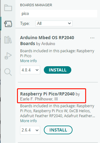
Click Tools > Development Board > Board Manager > Search pico, as my computer has already been installed, it shows that it is installed


Upload Demo at the First Time
-
Press and hold the BOOTSET button on the Pico board, connect the pico to the USB port of the computer via the Micro USB cable, and release the button after the computer recognizes a removable hard disk (RPI-RP2).

- Download the program and open D1-LED.ino under the arduino\PWM\D1-LED path
-
Click Tools --> Port, remember the existing COM, do not click this COM (the COM displayed is different on different computers, remember the COM on your own computer)

-
Connect the driver board to the computer using a USB cable. Then, go to Tools > Port. For the first connection, select uf2 Board. After uploading, when you connect again, an additional COM port will appear

-
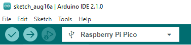
Click Tools > Development Board > Raspberry Pi Pico > Raspberry Pi Pico or Raspberry Pi Pico 2

- After setting it up, click the right arrow to upload the program


- If issues arise during this period, and if you need to reinstall or update the Arduino IDE version, it is necessary to uninstall the Arduino IDE completely. After uninstalling the software, you need to manually delete all contents within the C:\Users\[name]\AppData\Local\Arduino15 folder (you need to show hidden files to see this folder). Then, proceed with a fresh installation.
Open Source Demos
MircoPython video demo (github)
MicroPython firmware/Blink demos (C)
Raspberry Pi official C/C++ demo (github)
Raspberry Pi official micropython demo (github)
Arduino official C/C++ demo (github)
GUI API Details
If you have used our SPI screen before, you should be familiar with this example program
C
Underlying Hardware Interfaces
We have encapsulated the underlying layer, and due to different hardware platforms, the internal implementation is different. If you need to understand the internal implementation, you can check the corresponding directory
You can see a lot of definitions in DEV_Config.c(.h), which can be found in the directory: c\lib\Config
- Data type:
#define UBYTE   uint8_t
#define UWORD   uint16_t
#define UDOUBLE uint32_t
- Module initialization and exit processing:
void DEV_Module_Init(void);
void DEV_Module_Exit(void);
Note:
1. Here are some GPIOs before and after using the LCD screen.
- GPIO read/write:
void 	DEV_Digital_Write(UWORD Pin, UBYTE Value);
UBYTE 	DEV_Digital_Read(UWORD Pin);
- SPI write data:
void DEV_SPI_WriteByte(UBYTE Value);
Upper Layer Applications
For the screen, what if you need to paint, display Chinese and English characters, display pictures, etc., these are all done by the upper layer applications. Many of you have asked about some graphics processing, and we have provided some basic functions here
The GUI can be found in the directory: c\lib\GUI\GUI_Paint.c(.h)

In the following directory are the character fonts that the GUI depends on: c\lib\Fonts

- New Image Property: Create a new image property that includes the name, width, height, angle of rotation, and color of the image cache
void Paint_NewImage(UWORD *image, UWORD Width, UWORD Height, UWORD Rotate, UWORD Color)
Parameters:
 	image:  The name of the image cache, which is actually a pointer to the first address of the image cache;
 	Width:  The width of the image cache;
 	Height: The height of image cache;
 	Rotate: The angle of image rotation;
 	Color:  The initial color of the image;
- Select Image Cache: The purpose of selecting the image cache is that you can create multiple image properties, and there can be multiple image caches. You can select each image you create
void Paint_SelectImage(UBYTE *image)
Parameters:
 	image: The name of the image cache, which is actually a pointer to the first address of the image cache;
- Image Rotation: Set the rotation angle of the selected image, preferably after Paint_SelectImage (), you can choose to rotate 0, 90, 180, 270
void Paint_SetRotate(UWORD Rotate)
Parameters:
 	Rotate: Image rotation angles can be chosen as ROTATE_0, ROTATE_90, ROTATE_180, ROTATE_270 corresponding to 0, 90, 180, 270 degrees
- 【Note】Under different selection angles, the coordinates correspond to different starting pixels. Here taking 1.14 as an example, there are four images in sequence: 0°, 90°, 180°, 270°. For reference only


- Image Mirror Flip: Set the mirror flip of the selected image, you can choose no mirroring, horizontal mirroring, vertical mirroring, and mirroring around the image center
void Paint_SetMirroring(UBYTE mirror)
Parameters:
 	mirror: The mirroring method of the image can be selected as MIRROR_NONE, MIRROR_HORIZONTAL, MIRROR_VERTICAL, and MIRROR_ORIGIN, which correspond to no mirroring, horizontal mirroring, vertical mirroring, and mirroring around the image center, respectively
- Set the position and color of the point to be displayed in the cache: This is the core function of the GUI, handling point position and color displayed in the cache;
void Paint_SetPixel(UWORD Xpoint, UWORD Ypoint, UWORD Color)
Parameters:
 	Xpoint: The X position of the point in the image cache
 	Ypoint: The Y position of the point in the image cache
 	Color:  The color of the point
- Image cache fill color: Fill the image cache with a certain color, which is generally used as a screen whitening
void Paint_Clear(UWORD Color)
Parameters:
 	Color: The filled color
- Fill color of image cache window: Fill a certain part of the image cache window with a certain color, usually used as a window whitening function, commonly used for displaying time, whitening for one second
void Paint_ClearWindows(UWORD Xstart, UWORD Ystart, UWORD Xend, UWORD Yend, UWORD Color)
Parameters:
 	Xstart: The starting point X coordinate of the window
 	Ystart: The starting point Y coordinate of the window
 	Xend:   The endpoint X coordinate of the window
 	Yend:   The endpoint Y coordinate of the window
 	Color:  The filled color
- Draw a dot: In the image cache, draw a dot at (Xpoint, Ypoint), you can choose the color, the size, and the style of the dot
void Paint_DrawPoint(UWORD Xpoint, UWORD Ypoint, UWORD Color, DOT_PIXEL Dot_Pixel, DOT_STYLE Dot_Style)
Parameters:
 	Xpoint: The X coordinate of the dot
 	Ypoint: The Y coordinate of the dot
 	Color:  The filled color
 	Dot_Pixel: The size of the dots, which provides the default 8 sizes of dots
 	 	 typedef enum {
 	 	 	 DOT_PIXEL_1X1  = 1,		// 1 x 1
 	 	 	 DOT_PIXEL_2X2  , 		// 2 X 2
 	 	 	 DOT_PIXEL_3X3  , 	 	// 3 X 3
 	 	 	 DOT_PIXEL_4X4  , 	 	// 4 X 4
 	 	 	 DOT_PIXEL_5X5  , 		// 5 X 5
 	 	 	 DOT_PIXEL_6X6  , 		// 6 X 6
 	 	 	 DOT_PIXEL_7X7  , 		// 7 X 7
 	 	 	 DOT_PIXEL_8X8  , 		// 8 X 8
 	 	} DOT_PIXEL;
 	Dot_Style: The style of the dot, the method to expand the size of the dot is that, whether to expand from the dot as the center or from the dot as the lower left corner to the upper right
 	 	typedef enum {
 	 	   DOT_FILL_AROUND  = 1,
 	 	   DOT_FILL_RIGHTUP,
 	 	} DOT_STYLE;
- Draw a line: In the image cache, you can draw a line from (Xstart, Ystart) to (Xend, Yend) and choose the color, the width and the style of the line
void Paint_DrawLine(UWORD Xstart, UWORD Ystart, UWORD Xend, UWORD Yend, UWORD Color, LINE_STYLE Line_Style , LINE_STYLE Line_Style)
Parameters:
 	Xstart: The starting point X coordinate of the line
 	Ystart: The starting point Y coordinate of the line
 	Xend:   The endpoint X coordinate of the line
 	Yend:   The endpoint Y coordinate of the line
 	Color:  The filled color
 	Line_width: The width of the lines, which provides the default 8 widths
 	 	typedef enum {
 	 	 	 DOT_PIXEL_1X1  = 1,		// 1 x 1
 	 	 	 DOT_PIXEL_2X2  , 		// 2 X 2
 	 	 	 DOT_PIXEL_3X3  ,		// 3 X 3
 	 	 	 DOT_PIXEL_4X4  ,		// 4 X 4
 	 	 	 DOT_PIXEL_5X5  , 		// 5 X 5
 	 	 	 DOT_PIXEL_6X6  , 		// 6 X 6
 	 	 	 DOT_PIXEL_7X7  , 		// 7 X 7
 	 	 	 DOT_PIXEL_8X8  , 		// 8 X 8
 	 	} DOT_PIXEL;
 	 Line_Style: The style of the line, which selects whether the line is connected in a straight line or as a dashed line
 	 	typedef enum {
 	 	 	 LINE_STYLE_SOLID = 0,
 	 	 	 LINE_STYLE_DOTTED,
 	 	} LINE_STYLE;
- Draw a rectangle: In the image cache, you can draw a rectangle from (Xstart, Ystart) to (Xend, Yend) and choose the color, the width of the line, and whether to fill the inside of the rectangle
void Paint_DrawRectangle(UWORD Xstart, UWORD Ystart, UWORD Xend, UWORD Yend, UWORD Color, DOT_PIXEL Line_width, DRAW_FILL Draw_Fill)
Parameters:
 	Xstart: The starting point X coordinate of the rectangle
 	Ystart: The starting point Y coordinate of the rectangle
 	Xend:   The endpoint X coordinate of the rectangle
 	Yend:   The endpoint Y coordinate of the rectangle
 	Color:  The filled color
 	Line_width: The width of the four sides of the rectangle, providing the default 8 widths
 	 	typedef enum {
 	 	 	 DOT_PIXEL_1X1  = 1,		// 1 x 1
 	 	 	 DOT_PIXEL_2X2  , 		// 2 X 2
 	 	 	 DOT_PIXEL_3X3  ,		// 3 X 3
 	 	 	 DOT_PIXEL_4X4  ,		// 4 X 4
 	 	 	 DOT_PIXEL_5X5  , 		// 5 X 5
 	 	 	 DOT_PIXEL_6X6  , 		// 6 X 6
 	 	 	 DOT_PIXEL_7X7  , 		// 7 X 7
 	 	 	 DOT_PIXEL_8X8  , 		// 8 X 8
 	 	} DOT_PIXEL;
 	Draw_Fill: Filling, whether to fill the inside of the rectangle
 	 	typedef enum {
 	 	 	 DRAW_FILL_EMPTY = 0,
 	 	 	 DRAW_FILL_FULL,
 	 	} DRAW_FILL;
- Draw a circle: In the image cache, draw a circle with a radius of Radius with (X_Center Y_Center) as the center of the circle, and you can choose the color, the width of the line, and whether to fill the inside of the circle
void Paint_DrawCircle(UWORD X_Center, UWORD Y_Center, UWORD Radius, UWORD Color, DOT_PIXEL Line_width, DRAW_FILL Draw_Fill)
Parameters:
 	X_Center: The X coordinate of the center of the circle
 	Y_Center: The Y coordinate of the center of the circle
 	Radius:  The radius of the circle
 	Color:    The filled color
 	Line_width: The width of the arc, which provides the default 8 widths
 	 	typedef enum {
 	 	 	 DOT_PIXEL_1X1  = 1,		// 1 x 1
 	 	 	 DOT_PIXEL_2X2  , 		// 2 X 2
 	 	 	 DOT_PIXEL_3X3  ,		// 3 X 3
 	 	 	 DOT_PIXEL_4X4  ,		// 4 X 4
 	 	 	 DOT_PIXEL_5X5  , 		// 5 X 5
 	 	 	 DOT_PIXEL_6X6  , 		// 6 X 6
 	 	 	 DOT_PIXEL_7X7  , 		// 7 X 7
 	 	 	 DOT_PIXEL_8X8  , 		// 8 X 8
 	 	} DOT_PIXEL;
 	Draw_Fill: Filling, whether to fill the inside of the circle
 	 	typedef enum {
 	 	 	 DRAW_FILL_EMPTY = 0,
 	 	 	 DRAW_FILL_FULL,
 	 	} DRAW_FILL;
- Write Ascii characters: In the image cache, with (Xstart Ystart) as the left vertex, write an Ascii character, and you can select the Ascii code visual character font library, font foreground color, and font background color
void Paint_DrawChar(UWORD Xstart, UWORD Ystart, const char Ascii_Char, sFONT* Font, UWORD Color_Foreground, UWORD Color_Background)
Parameters:
 	Xstart: The left vertex X coordinate of the character
 	Ystart: The left vertex Y coordinate of the character
 	Ascii_Char: Ascii character
 	Font: The Ascii code visual character font library, provides the following fonts in the Fonts folder:
 	 	font8: 5*8 font
 	 	font12: 7*12 font
 	 	font16: 11*16 font
 	 	font20: 14*20 font
 	 	font24: 17*24 font
 	Color_Foreground: Font color
 	Color_Background: Background color
- Write English strings: In the image cache, write a string of English characters with (Xstart Ystart) as the left vertex, and you can select the Ascii code visual character font library, font foreground color, and font background color
void Paint_DrawString_EN(UWORD Xstart, UWORD Ystart, const char * pString, sFONT* Font, UWORD Color_Foreground, UWORD Color_Background)
Parameters:
 	Xstart:  The left vertex X coordinate of the character
 	Ystart:  The left vertex Y coordinate of the character
 	pString: A string, a string is a pointer
 	Font: The Ascii code visual character font library, provides the following fonts in the Fonts folder:
 	 	font8: 5*8 font
 	 	font12: 7*12 font
 	 	font16: 11*16 font
 	 	font20: 14*20 font
 	 	font24: 17*24 font
 	Color_Foreground: Font color
 	Color_Background: Background color
- Write Chinese strings: In the image cache, write a string of Chinese characters with (Xstart Ystart) as the left vertex, and you can select the GB2312 encoding character font library, font foreground color, and font background color
void Paint_DrawString_CN(UWORD Xstart, UWORD Ystart, const char * pString, cFONT* font, UWORD Color_Foreground, UWORD Color_Background)
Parameters:
 	Xstart:  The left vertex X coordinate of the character
 	Ystart:  The left vertex Y coordinate of the character
 	pString: A string, a string is a pointer
 	Font: The GB2312 encoding character library, the following fonts are provided in the Fonts folder:
 	 	font12CN: Ascii character font 11*21, Chinese font 16*21
 	 	font24CN: Ascii character font 24*41, Chinese font 32*41
 	Color_Foreground: Font color
 	Color_Background: Background color
- Write numbers: In the image cache, write a string of numbers with (Xstart Ystart) as the left vertex, and you can select the Ascii code visual character font library, font foreground color, and font background color
void Paint_DrawNum(UWORD Xpoint, UWORD Ypoint, double Nummber, sFONT* Font, UWORD Digit,UWORD Color_Foreground, UWORD Color_Background);
Parameters:
 	Xstart:  The left vertex X coordinate of the character
 	Ystart:  The left vertex Y coordinate of the character
 	Number: The displayed number, here is stored in a 32-bit long int type, which can be displayed up to 2147483647.
 	Font: The Ascii code visual character font library, provides the following fonts in the Fonts folder:
 	 	font8: 5*8 font
 	 	font12: 7*12 font
 	 	font16: 11*16 font
 	 	font20: 14*20 font
 	 	font24: 17*24 font
        Digit: Display decimal places
 	Color_Foreground: Font color
 	Color_Background: Background color
- Display time: In the image cache, display time with (Xstart Ystart) as the left vertex, and you can select the Ascii code visual character font library, font foreground color, and font background color
void Paint_DrawTime(UWORD Xstart, UWORD Ystart, PAINT_TIME *pTime, sFONT* Font, UWORD Color_Background, UWORD Color_Foreground)
Parameters:
 	Xstart: The left vertex X coordinate of the character
 	Ystart: The left vertex Y coordinate of the character
 	pTime:  The displayed time, here defines a time structure, just pass the numbers of the hour, minute, second to the parameters
 	Font: The Ascii code visual character font library, provides the following fonts in the Fonts folder:
 	 	font8: 5*8 font
 	 	font12: 7*12 font
 	 	font16: 11*16 font
 	 	font20: 14*20 font
 	 	font24: 17*24 font
 	Color_Foreground: Font color
 	Color_Background: Background color
QMI8658
- Module initialization
unsigned char QMI8658_init(void);
- Read data
void QMI8658_read_xyz(float acc[3], float gyro[3], unsigned int *tim_count);
Parameters:
	 float acc[3]: The array that stores acceleration values, represented as floating-point numbers, contains three elements, which are acceleration on the X, Y, and Z axes
	 float gyro[3]: The array that stores gyroscope values, represented as floating-point numbers, contains three elements, which are angular velocities on the X, Y, and Z axes
Python
Underlying Hardware Interface
- Module initialization
def __init__(self)
- Send a command
def write_cmd(self, cmd)
- Send data
def write_data(self, buf)
- Adjust backlight
def set_bl_pwm(self,duty)
Drawing GUI
- Import a library
import framebuf
- Create an object
The custom class LCD_1inch28 inherits the framebuf.FrameBuffer class from MicroPython, which provides many methods to draw images, let's create the LCD_1inch28 class object first
LCD = LCD_1inch28()
- Draw a line
LCD.line(x1, y1, x2, y2, color)
Parameters:
	x1, y1: The x and y coordinates of the starting point
	x2, y2: The x and y coordinates of the endpoint
	color:  The color of the line
- Draw a rectangle
LCD.fill_rect(x1, y1, w, h, color)
Parameters:
	x1, y1: The x and y coordinates of the upper left corner of the rectangle
        w, h:   The width and height of the rectangle
        color:  The filling color of the rectangle
- Draw text
LCD.text(str, x, y, color)
Parameters:
         str:   Display text
	 x, y:  The x and y coordinates of the upper left corner of the text
         color: The color of the text
- Change the text size
LCD.write_text(str, x, y, size, color)
Parameters:
	 size: The difference between this function and LCD.text is that it supports custom font size, which is used to specify the font size
- Display
LCD.show()
QMI8658
- Create an object
qmi8658=QMI8658()
- Read and parse the XYZ data of the sensor
xyz=qmi8658.Read_XYZ()
Return values:
          xyz[0]~xyz[2]: The function returns an array, with the first three elements representing acceleration on the X, Y, and Z axes
	  xyz[3]~xyz[5]: These three elements represent the angular velocities on the X, Y, and Z axes
LVGL Demo
Example Effect
The demonstration displays two interfaces that can be switched by either sliding on the touchscreen or tilting with the six-axis sensor.
- The first interface:
- Display content: Waveshare Logo

- Display content: Waveshare Logo
- The second interface
- Display content: 6-axis sensor data
- Refresh frequency: Updated every 500ms.
- Switch mode: Utilize the six-axis sensor to trigger the input device confirmation event by lifting it to the right to select the interface. Lift it upward again to trigger the switch event for interface navigation.


Demo
This example is for testing LVGL control interaction, styling, etc. For details, you can refer to LVGL development document.
Source Code Structure
- The source code of the LVGL library is in ./lib/lvgl, and the version is 8.1. For the secondary development, you can refer to the development document.
- The related setting of the LVGL library is in ./examples/inc/lv_conf.h, and you can set the display refreshing rate, the system occupied data, and so on.

- The application code of the LVGL library is in ./examples/src/LVGL_example.c.


Implement Functions
- This example utilizes DMA for transferring color data to the SPI bus, reducing CPU utilization. The CPU usage remains below 20% during simple interactions, and memory usage stays below 30%.
- The system clock in this example runs at 270MHz. The peripheral clock frequency of the SPI is set to match the system clock. Additionally, the LVGL library's double buffering mechanism is employed, ensuring smooth animations by rendering one buffer while transferring data in the other.
- A six-axis simulator is used in this example, emulating gyroscope data as input for encoder devices, which can be applied in various interactive scenarios.
Compile and Run
- Pico VSCode
-
Select the project directory and import the project

-
Select the version and SDK version, click Compile to compile


- Windows
- Refer to Windows Environment Setup Tutorial to complete the environment setup
- Open VS 2022 -> Tool -> Command Line -> Developer Powershell
- Set the absolute address of pico-sdk as PICO_SDK_PATH, for example, set pico-sdk address as "D:\pico\pico-sdk"
setx PICO_SDK_PATH "D:\pico\pico-sdk"
- Download the demo, enter the source code directory, if the build directory already exists, you can go directly into it. If not, you can create this directory:
mkdir build
cd build
- Execute cmake, automatically generate the Makefile file:
cmake -G "NMake Makefiles" ..
- Execute nmake to generate the executable file, and input the following content in the terminal:
nmake
After compilation, it will generate a .uf2 formatted file. - Press the onboard boot key, connect the board to the USB interface of the PC through a Micro USB cable. And then release the key, the PC will identify the pico as a removable driver. Finally, you need to copy the compiled file in .uf2 format to Pico.
- Ubuntu
- Refer to Chapter 2. The SDK of Getting started with Raspberry Pi Pico to complete the environment setup
- Open a terminal, set the value of the environment variable PICO_SDK_PATH to the absolute path of pico-sdk, for example, if my pico-sdk path is "/home/pico/pico-sdk"
nano ~/.bashrc
#Add the following content at the last line
export PICO_SDK_PATH="/home/pico/pico-sdk"
- After setting, save and exit. The configuration takes effect
source ~/.bashrc
- Download the demo, enter the source code directory, if the build directory already exists, you can go directly into it. If not, you can create this directory:
mkdir build
cd build
- Execute cmake, it will generate Makefile file:
cmake ..
- Execute nmake to generate the executable file, and input the following content in the terminal:
nmake
After compilation, it will generate a .uf2 formatted file. - Press the onboard boot key, connect the board to the USB interface of the PC through a Micro USB cable. And then release the key, the PC will identify the pico as a removable driver. Finally, you need to copy the compiled file in .uf2 format to Pico.
Source Code Analysis
LVGL Initialization
- Initialization function:
- FunctionL For initializing all the hardware and structure variables required for LVGL.
void LVGL_Init(void);
- LVGL Library Core Structure Variable Definition
- Definition Function: The initialization process of the LVGL library mainly involves initializing several core structure variables of LVGL. The operation of the LVGL library relies on these core structure variables.
- Definition Method: Setting the sizes of buf0 and buf1 to half the screen display area is aimed at implementing the LVGL double buffering mechanism. This mechanism helps reduce noticeable jagged edges during extensive screen redraws while effectively enhancing the screen refresh rate. When using a single buffer, it's preferable to set it to 10% of the screen display area to significantly reduce system occupancy. However, this setup may result in more apparent jagged edges during extensive image refreshes.
// LVGL
static lv_disp_draw_buf_t disp_buf;                   //LVGL display buffer
static lv_color_t buf0[DISP_HOR_RES * DISP_VER_RES/2];//LVGL color data buffer 0
static lv_color_t buf1[DISP_HOR_RES * DISP_VER_RES/2];//LVGL color data buffer 1
static lv_disp_drv_t disp_drv;                        //LVGL display driver

static lv_indev_drv_t indev_en;                       //LVGL 6-axis sensor analog encoder input device driver
static lv_group_t *group;                             //Encoder control group
- How to realize the initialization of the LVGL library
- Function: improve the core structure variables of the LVGL library.
- Method: The encoder input device of the LVGL library has both an edit mode and a browse mode. In the browse mode, triggering a switch event will change the selected control within the control group. Triggering a confirmation event will transition the selected control into edit mode. Therefore, when simulating an encoder with a six-axis sensor, it's essential to introduce the 'lv_group_t' structure variable as the control group for the six-axis sensor.
// Initialize LVGL core
lv_init();

// Initialize the LVGL display buffer structure variable disp_buf
lv_disp_draw_buf_init(&disp_buf, buf0, buf1, DISP_HOR_RES * DISP_VER_RES / 2);
lv_disp_drv_init(&disp_drv);
disp_drv.flush_cb = disp_flush_cb;
disp_drv.draw_buf = &disp_buf;
disp_drv.hor_res = DISP_HOR_RES;
disp_drv.ver_res = DISP_VER_RES;
lv_disp_t *disp= lv_disp_drv_register(&disp_drv);

// Initialize the encoder input device
lv_indev_drv_init(&indev_en);
indev_en.type = LV_INDEV_TYPE_ENCODER;
indev_en.read_cb = encoder_read_cb;
lv_indev_t * encoder_indev = lv_indev_drv_register(&indev_en);
group = lv_group_create();
lv_indev_set_group(encoder_indev, group);//Adding encoder control devices to a control group
- Run the LVGL library:
- Function: The LVGL library calls the function lv_tick_inc periodically to inform LVGL about the passage of time. This allows LVGL to update its internal time status and handle time-related tasks such as animations and timers. Additionally, within the main function loop, the lv_task_handler function needs to be called to manage predefined tasks.
- Implementation method: It's crucial to ensure that the priority of lv_task_handler is lower than that of lv_tick_inc. Therefore, in this example, lv_tick_inc is called within a timer callback function.
- Function: The LVGL library calls the function lv_tick_inc periodically to inform LVGL about the passage of time. This allows LVGL to update its internal time status and handle time-related tasks such as animations and timers. Additionally, within the main function loop, the lv_task_handler function needs to be called to manage predefined tasks.
add_repeating_timer_ms(5, repeating_lvgl_timer_callback, NULL, &lvgl_timer);//Timer callback function called every 5ms

static bool repeating_lvgl_timer_callback(struct repeating_timer *t)
{
    lv_tick_inc(5);
    return true;
}

int main()
{
    ...
    while(1)
    {
      lv_task_handler();
      DEV_Delay_ms(5);
    }

}
LVGL Display
- LVGL shows callback functions
- Function: mainly accomplishes the drawing of the image in the refresh area.
void disp_flush( lv_disp_drv_t *disp_drv, const lv_area_t *area, lv_color_t *color_p )
Parameters:
    lv_disp_drv_t *disp_drv: Display driver structure pointer, which contains information and function pointers related to the display. This parameter is commonly used to signal the completion of a refresh
    const lv_area_t *area: Region structure pointer, containing positional information of the area to be refreshed. In this example, used for creating a window for TFT display
    lv_color_t *color_p: color structure pointer, Color data representing what needs to be displayed within the refresh area. In this case, acting as DMA input read address to transfer data to the SPI bus, completing the drawing of the image
- LVGL display color setting:
- Target: The pixel color storage method built by the lv_color_t structure in its default state is inconsistent with the data required for transmission in this example. Direct transmission would result in color discrepancies in the displayed image.
- Method: Modify the settings in the lv_conf.h folder to change how colors are stored.
#define LV_COLOR_16_SWAP 1
- LVGL displays the refresh rate setting
- Method: in "lv_conf.h", you can also set the refresh rate time for the display buffer. Modifying this definition allows you to change the screen's refresh rate.
#define LV_DISP_DEF_REFR_PERIOD 10 /*[ms]*/
- LVGL Display Callback Function Implementation
- Implementation Method: In this example, to maximize the reduction in processor utilization, DMA is utilized for the transfer of color data. 'color_p' is set as the read address, and the output data register of the SPI bus is set as the write address.
static void disp_flush_cb(lv_disp_drv_t * disp, const lv_area_t * area, lv_color_t * color_p)
{

    LCD_1IN28_SetWindows(area->x1, area->y1, area->x2 , area->y2);//Set the display area of the image
    dma_channel_configure(dma_tx,
                          &c,
                          &spi_get_hw(LCD_SPI_PORT)->dr,          //SPI bus output data register address
                          color_p,                                //Address of the color data array to be refreshed
                          ((area->x2 + 1 - area-> x1)*(area->y2 + 1 - area -> y1))*2,
                          true                                    //Transfer immediately after setup
                          );
}
- LVGL Refresh Completion Notification Implementation
- Functionality: It's necessary to notify the LVGL core after each image refresh is completed so that LVGL can prepare for rendering the next refresh image.
- Implementation Method: In this example, the LVGL image refresh completion is notified within the DMA transfer completion interrupt service function. Using a blocking notification mechanism would prevent leveraging the double buffering mechanism to enhance the refresh speed.
static void dma_handler(void)
{
    if (dma_channel_get_irq0_status(dma_tx)) {
        dma_channel_acknowledge_irq0(dma_tx);
        lv_disp_flush_ready(&disp_drv);
    }
}
LVGL Input
- The input callback function of the LVGL.
- Implementation Method: for refreshing the input events.
static void encoder_read_cb(lv_indev_drv_t * drv, lv_indev_data_t*data);
Parameter:
  lv_indev_drv_t *indev_drv: Pointer to the input device driver structure in LVGL. In this example, the structure represents the input device driver for an encoder simulated by a six-axis sensor.
  lv_indev_data_t *data: Pointer to the input device data structure in LVGL. In this example, the structure is used to store the state and data of the input device, including the current switch event (up or down) and confirmation event (right lift)
- LVGL Frequency Settings for Calling Input Device Callback Functions
- Method: LVGL defaults to call the input device callback function every 30ms to update the events triggered by the input device, which can be set in lv_conf.h.
#define LV_INDEV_DEF_READ_PERIOD 30 /*[ms]*/
- Six-axis sensor input device callback function implementation
- Operation: The six-axis sensor analog encoder is used as an input device, with up and down lifts triggering switching events and right lifts triggering OK events.
- Implementation: Since the data of the six-axis sensor changes more frequently, to minimize the misoperation of the situation use a timed multiple sampling method to update the device switching event and determine the event.
static bool repeating_imu_diff_timer_callback(struct repeating_timer *t);//Input events updated every 50ms
{
    get_diff_data();//Multi-sampling recognizes input events updating the global variables encoder_diff and encoder_act.
    return true;
}

static void encoder_read_cb(lv_indev_drv_t * drv, lv_indev_data_t*data)
{
  data->enc_diff = encoder_diff;
  data->state    = encoder_act;
}
LVGL Control Layout
- LVGL Control Initialization
- Function: for styling controls and laying out controls.
void Widgets_Init(void);
- LVGL Control Creating Function
- Function: Creating controls requires using different function interfaces for different controls. It's possible to choose a parent object for creation.
lv_obj_t *btn = lv_btn_create(lv_scr_act()); //Create a control where the lv_scr_act layer is the parent of the button, which can be replaced by a list, title, etc. that can have children
- Alignment Positioning of LVGL Controls
- Function: Enables the control to be positioned offset based on a reference point. The center of the reference point control to which the control is aligned for the offset.
- Alignment standard: The LVGL library has both internal and external alignment. By default, the top-left corner is used as the origin, left is the positive horizontal direction, and down is the positive vertical direction.
lv_obj_align(btn, LV_ALIGN_CENTER, -50 , 50);//Position the btn control 50 pixels left of center and 50 pixels down

- Styling of LVGL controls
- Function: Enables the control to be rendered according to a set style. Using the lv_obj_add_style function you can realize the rendering of each part of the control in different states.
static lv_style_t style_base;
lv_style_init(&style_base);                                                          //Initialize the style
lv_style_set_bg_color(&style_base, lv_palette_main(LV_PALETTE_LIGHT_GREEN));         //Set the background color
lv_style_set_border_color(&style_base, lv_palette_darken(LV_PALETTE_LIGHT_GREEN, 3));//Set the border color
lv_style_set_border_width(&style_base, 2);                                           //Set the edit width
lv_style_set_radius(&style_base, 10);                                                //Setting the size of the corner radius
lv_style_set_shadow_width(&style_base, 10);                                          //Set the width of the shadow

lv_obj_add_style(btn,&style_base,0);                                                 //Set the style of the btn theme, 0 can be replaced by the position and state

Before stylization After stylization
- LVGL control group add function
- Function: Incorporates the LVGL control into a control group so that the encoder input device can enter edit mode to modify the state of the control.
lv_group_add_obj(group, btn);//Add the btn control to the group of controls
Resource
Demo
- Demo code
- LVGL Demo code
- Clock project shared by Wienzek Daniel
- Demo codes based on PlatformIO, shared by Philipp Molitor
Drawing
Datasheet
Official Raspberry Pi Documents
- Raspberry Pi Pico MicroPython Book
- Raspberry Pi related books
- Pico datasheet
- RPI-PICO-R3-PUBLIC-SCHEMATIC
- Pico R3 A4 Pinout
- Getting started with pico
- Pico c sdk
- Pico python sdk.pdf
- Pico datasheet
- Rp2040 datasheet
- Hardware design with rp2040
Raspberry Pi Demo
Development Software
- Zimo221.7z
- Image2Lcd.7z
- Font Library Tutorial
- Image Extraction Tutorial
- Thonny Python IDE (Windows V3.3.3)
FAQ
It is connected directly to the RP2040 chip, you cannot do this by calling a specific GPIO number etc., this is a fixed pin.
{{{5}}}
Download the attached zip file, and then follow the instructions as per the attached video file, or you can check this https://github.com/Melvinsajith/raspberrry_Pi_Pico_windows_7_8_xp
{{{5}}}
Please flash the attached firmware:
https://files.waveshare.com/wiki/RP2040-LCD-1.28/flash_nuke.uf2
{{{5}}}
- The micropython firmware does not have this library, so it cannot be imported.
- This is a simple import method made by our engineers to see if it meets your requirements (see the attachment).
- How to use: You need to save QMI8658.py to Pico first, and then use from QMI8658 import QMI8658 to import it into your own function. You can also directly use the RP2040-LCD-1.28.py in our compressed package. Has been tested in RP2040-LCD-1.28.
- XKF3 is introduced in the manual and is used as a supporting sensor. we didn't use this.
{{{5}}}
Support
Technical Support
If you need technical support or have any feedback/review, please click the Submit Now button to submit a ticket, Our support team will check and reply to you within 1 to 2 working days. Please be patient as we make every effort to help you to resolve the issue.
Working Time: 9 AM - 6 PM GMT+8 (Monday to Friday)