
Pico Eval Board
| ||

Overview
Introduction
- A function evaluation board specially designed for Raspberry Pi Pico.
- Rich onboard resources are available to help users get started and learn quickly.
Features
- Standard Raspberry Pi Pico header supports Raspberry Pi Pico series boards.
- 3.5-inch resistive touch screen, 65K colorful, bringing clear and vivid display effect.
- Standard 3.5mm audio jack, for headphones or other audio peripherals.
- Micro SD card slot through the SDIO interface, faster access speed than SPI interface.
- Integrates battery header and recharge circuit, allowing it to keep running without a wired power supply.
- Other rich resources like a buzzer, photoresistor, and RGB LED.
Specifications
| LCD Parameters | |||
| Control Chip | ILI9488 | Resolution | 480 × 320 Pixels |
| Communication Interface | SPI | Display Size | 73.44 × 48.96 mm |
| Display Panel | IPS | Pixel Size | 0.153 × 0.153 mm |
| ICM20948 Parameters | |||
| Accelerometer Characteristics | Resolution: 16 bits Range (optional): ±2, ±4, ±8, ±16g Operating Current: 68.9uA | ||
| Gyroscope Characteristics | Resolution: 16 bits Range (optional): ±250, ±500, ±1000, ±2000°/sec Operating Current: 1.23mA | ||
| Magnetometer Characteristics | Resolution: 16 bits Range: ±4900µT Operating Current: 90uA | ||
Pinout

Video
Dimension

Pico Getting Started
Firmware Download
- MicroPython Firmware Download

- C_Blink Firmware Download

Introduction
MicroPython Series
Install Thonny IDE
In order to facilitate the development of Pico/Pico2 boards using MicroPython on a computer, it is recommended to download the Thonny IDE
- Download Thonny IDE and follow the steps to install, the installation packages are all Windows versions, please refer to Thonny's official website for other versions
- After installation, the language and motherboard environment need to be configured for the first use. Since we are using Pico/Pico2, pay attention to selecting the Raspberry Pi option for the motherboard environment

- Configure MicroPython environment and choose Pico/Pico2 port
- Connect Pico/Pico2 to your computer first, and in the lower right corner of Thonny left-click on the configuration environment option --> select Configture interpreter
- In the pop-up window, select MicroPython (Raspberry Pi Pico), and choose the corresponding port


Flash Firmware
- Click OK to return to the Thonny main interface, download the corresponding firmware library and flash it to the device, and then click the Stop button to display the current environment in the Shell window
- Note: Flashing the Pico2 firmware provided by Micropython may cause the device to be unrecognized, please use the firmware below or in the package
- How to download the firmware library for Pico/Pico2 in windows: After holding down the BOOT button and connecting to the computer, release the BOOT button, a removable disk will appear on the computer, copy the firmware library into it
- How to download the firmware library for RP2040/RP2350 in windows: After connecting to the computer, press the BOOT key and the RESET key at the same time, release the RESET key first and then release the BOOT key, a removable disk will appear on the computer, copy the firmware library into it (you can also use the Pico/Pico2 method)

MicroPython Series
【MicroPython】 machine.Pin class function details
【MicroPython】machine.PWM class function details
【MicroPython】machine.ADC class function details
【MicroPython】machine.UART class function details
【MicroPython】machine.I2C class function details
【MicroPython】machine.SPI class function details
【MicroPython】rp2.StateMachine class function details
C/C++ Series
For C/C++, it is recommended to use Pico VS Code for development. This is a Microsoft Visual Studio Code extension designed to make it easier for you to create, develop, and debug projects for the Raspberry Pi Pico series development boards. No matter if you are a beginner or an experienced professional, this tool can assist you in developing Pico with confidence and ease. Here's how to install and use the extension.
- Official website tutorial: https://www.raspberrypi.com/news/pico-vscode-extension/
- This tutorial is suitable for Raspberry Pi Pico, Pico2 and the RP2040 and RP2350 series development boards developed by Waveshare
- The development environment defaults to Windows11. For other environments, please refer to the official tutorial for installation
Install VSCode
-
First, click to download pico-vscode package, unzip and open the package, double-click to install VSCode

Note: If vscode is installed, check if the version is v1.87.0 or later


Install Extension
-
Click Extensions and select Install from VSIX

-
Select the package with the vsix suffix and click Install

-
Then vscode will automatically install raspberry-pi-pico and its dependency extensions, you can click Refresh to check the installation progress

-
The text in the right lower corner shows that the installation is complete. Close VSCode


Configure Extension
-
Open directory C:\Users\username and copy the entire .pico-sdk to that directory

-
The copy is completed

-
Open vscode and configure the paths for the Raspberry Pi Pico extensions

The configuration is as follows:Cmake Path: ${HOME}/.pico-sdk/cmake/v3.28.6/bin/cmake.exe Git Path: ${HOME}/.pico-sdk/git/cmd/git.exe Ninja Path: ${HOME}/.pico-sdk/ninja/v1.12.1/ninja.exe Python3 Path: ${HOME}/.pico-sdk/python/3.12.1/python.exe


New Project
-
The configuration is complete, create a new project, enter the project name, select the path, and click Create to create the project
To test the official example, you can click on the Example next to the project name to select
-
The project is created successfully


Compile Project
-
Select the SDK version

-
Select Yes for advanced configuration

-
Choose the toolchain, 13.2.Rel1 is applicable for ARM cores, RISCV.13.3 is applicable for RISCV cores. You can select either based on your requirements

-
Select Default for CMake version (the path configured earlier)

-
Select Default for Ninja version

-
Select the development board

-
Click Compile to compile

-
The .uf2 format file is successfully compiled


Flash Firmware
Here are two methods for flashing firmware
-
Flash firmware using the pico-vscode plugin
Connect the development board to the computer, click Run to flash the firmware directly
-
Flash the firmware manually
1. Press and hold the Boot button
2. Connect the development board to the computer
3. Then the computer will recognize the development board as a USB device.
4. Copy the .uf2 file to the USB drive, and the device will automatically restart, indicating successful program flashing.

Import Project
-
Select the project directory and import the project

- The Cmake file of the imported project cannot have Chinese (including comments), otherwise the import may fail
-
To import your own project, you need to add a line of code to the Cmake file to switch between pico and pico2 normally, otherwise even if pico2 is selected, the compiled firmware will still be suitable for pico

set(PICO_BOARD pico CACHE STRING "Board type")


Update Extension
-
The extension version in the offline package is 0.15.2, and you can also choose to update to the latest version after the installation is complete


Arduino IDE Series
Install Arduino IDE
-
First, go to Arduino official website to download the installation package of the Arduino IDE.

-
Here, you can select Just Download.

-
Once the download is complete, click Install.

Notice: During the installation process, it will prompt you to install the driver, just click Install


Arduino IDE Interface
-
After the first installation, when you open the Arduino IDE, it will be in English. You can switch to other languages in File --> Preferences, or continue using the English interface.

-
In the Language field, select the language you want to switch to, and click OK.


Install Arduino-Pico Core in the Arduino IDE
-
Open the Arduino IDE, click on the file in the top left corner, and select Preferences

-
Add the following link to the attached board manager URL, and then click OK
https://github.com/earlephilhower/arduino-pico/releases/download/4.0.2/package_rp2040_index.json

Note: If you already have an ESP32 board URL, you can use a comma to separate the URLs as follows:https://dl.espressif.com/dl/package_esp32_index.json,https://github.com/earlephilhower/arduino-pico/releases/download/4.0.2/package_rp2040_index.json
-
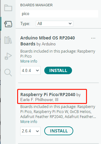
Click Tools > Development Board > Board Manager > Search pico, as my computer has already been installed, it shows that it is installed


Upload Demo at the First Time
-
Press and hold the BOOTSET button on the Pico board, connect the pico to the USB port of the computer via the Micro USB cable, and release the button after the computer recognizes a removable hard disk (RPI-RP2).

- Download the program and open D1-LED.ino under the arduino\PWM\D1-LED path
-
Click Tools --> Port, remember the existing COM, do not click this COM (the COM displayed is different on different computers, remember the COM on your own computer)

-
Connect the driver board to the computer using a USB cable. Then, go to Tools > Port. For the first connection, select uf2 Board. After uploading, when you connect again, an additional COM port will appear

-
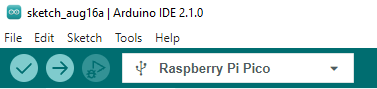
Click Tools > Development Board > Raspberry Pi Pico > Raspberry Pi Pico or Raspberry Pi Pico 2

- After setting it up, click the right arrow to upload the program


- If issues arise during this period, and if you need to reinstall or update the Arduino IDE version, it is necessary to uninstall the Arduino IDE completely. After uninstalling the software, you need to manually delete all contents within the C:\Users\[name]\AppData\Local\Arduino15 folder (you need to show hidden files to see this folder). Then, proceed with a fresh installation.
Open Source Demos
MircoPython video demo (github)
MicroPython firmware/Blink demos (C)
Raspberry Pi official C/C++ demo (github)
Raspberry Pi official micropython demo (github)
Arduino official C/C++ demo (github)
User Guides
Raspberry Pi
Download Demo
sudo apt-get install p7zip-full -y
cd ~
wget https://files.waveshare.com/upload/5/5a/Pico-Eval-Board-Code.zip
7z x Pico-Eval-Board-Code.zip -o./Pico-Eval-Board-Code
cd Pico-Eval-Board-Code
- Log in Raspberry Pi terminal by SSH or press Ctrl + Alt + T to open the terminal when using the screen.
- Load and decompress the program to the Pico C/C++ SDK directory, if the SDK has not been installed yet, please refer to the tutorial
C
- Press BOOTSEL on the Pico and connect Pico to the USB of Raspberry Pi by Micro USB cable.
- Compile and run the c example demo of the Pico-Eval-Board.
cd ./c/
There are corresponding demos in this directory. Different demos correspond to different peripherals and functions.
![]()
The following takes 01_GPIO as an example. The GPIO demo will make the LED on the Pico blink every second.
cd ./01_GPIO/build
cmake..
make -j
#If there is no connection or Pico in download mode will report an error
sudo cp ./*.uf2 /media/pi/RPI-RP2/
3. Run the corresponding demo on the Pico.
4. Press the Reset key on the Pico-Eval-Board to reset the Pico. Please press the Bootsel key first and the Run key, and then release the Reset key. By now, Pico enters disk mode without plugging or unplugging.
MicroPython
- According to the python environment configuration settings, use the Raspberry Pi desktop system.
- Open the Thonny IDE of the Raspberry Pi system, pull the code file into the IDE, save it to the Pico file system, and click the Run button.

Windows
C
Download the demo
Use the demo
1. Open the corresponding C program folder.

2. Open it by Vs code and choose the corresponding compile tool.

3. Click "Build" to compile:

4. Press the Reset button on the Pico-Eval-Board to reset the Pico, first press the BOOTSEL button and then the RUN button and then release the Reset button, the Pico can enter the disk mode without plugging and unplugging the Pico, and drag and drop the UF2 file under the build file to the RPI-RP2 drive letter.

5. At this point, Pico starts to run the corresponding program.
MicroPython
- Please refer to Video Tutorial
- Pico-wiki-tutorial
Resource
Document
Driver
Examples
Development Software
- Zimo221.7z
- Image2Lcd.7z
- Font Library Tutorial
- Image Extraction Tutorial
- Thonny Python IDE (Windows V3.3.3)
Support
Technical Support
If you need technical support or have any feedback/review, please click the Submit Now button to submit a ticket, Our support team will check and reply to you within 1 to 2 working days. Please be patient as we make every effort to help you to resolve the issue.
Working Time: 9 AM - 6 PM GMT+8 (Monday to Friday)