Details
Prohibited by the manufacturer Raspberry Pi, we're not allowed to ship this product, or to provide any tech support, to the following countries/regions: Cuba, Iran, North Korea, Syria, Crimea, Donetsk, Luhansk, Russia, Belarus.
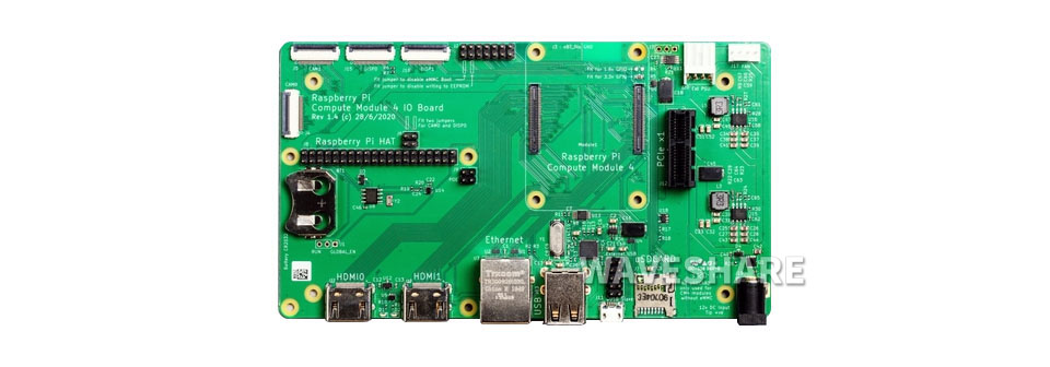
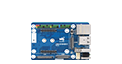
Raspberry Pi Compute Module 4 IO Board, a development platform and reference base-board design for CM4
Compute module 4 IO Board
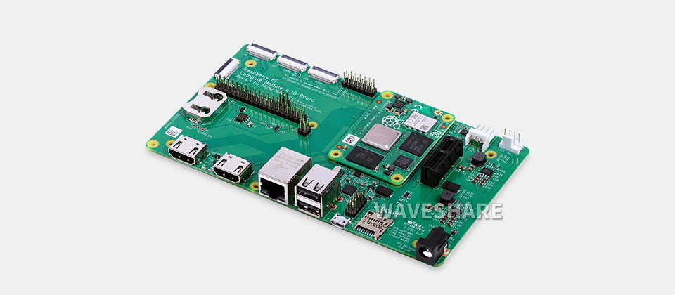
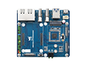
The Compute Module 4 IO Board is a companion board for Raspberry Pi Compute Module 4 (supplied separately). It is designed for use both as a development system for Compute Module 4 and as an embedded board integrated into end products.
The IO board is designed to allow you to create systems quickly using off-theshelf parts such as HATs and PCIe cards, which might include NVMe, SATA, networking, or USB. The major user connectors are located along one side to make enclosures simple.
Compute Module 4 IO Board also provides an excellent way to prototype systems using the Compute Module 4.
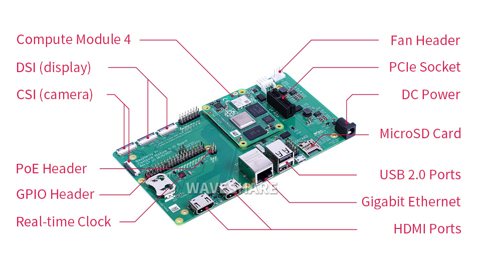
Interfaces introduction
Specifications
| CM4 socket | suitable for all variants of Compute Module 4 |
|---|---|
| Connectors | Standard Raspberry Pi HAT connectors with PoE support Standard PCIe Gen 2 x1 socket Various jumpers to disable specific features, e.g. wireless connectivity, EEPROM writing |
| RTC | Real-time clock with battery socket and ability to wake Compute Module 4 |
| Video | 2 x MIPI DSI display FPC connectors (22-pin 0.5 mm pitch cable) |
| Camera | 2 x MIPI CSI-2 camera FPC connectors (22-pin 0.5 mm pitch cable) |
| USB | 2 x USB 2.0 connectors Micro USB socket for updating Compute Module 4 |
| Ethernet | Gigabit Ethernet RJ45 with PoE support |
| Storage socket | MicroSD card socket for Compute Module 4 Lite (without eMMC) variants |
| Fan | Standard fan connector |
| Power input | 12V / 5V |
| Dimensions | 160 × 90mm |
CM4 base board selection guide
| CM4 Base Board | Interface count and specifications | |||||||||||
|---|---|---|---|---|---|---|---|---|---|---|---|---|
| PoE | Gigabit ETH |
40PIN GPIO |
PCIe | USB① | DSI | HDMI | CSI | RTC | Fan Header |
Power Input |
Features | |
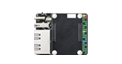
 NANO A |
√ | 2.0×1 | ×1 | 5V | CM4 sized | |||||||
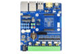
 NANO B |
×1 | √ | 2.0×1 | ×1 | ×1 | ×1 | 5V | CM4 sized | ||||
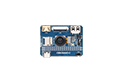 NANO C |
√ | 2.0×1 | ×1 | ×1 | ×1 | 5V | Onboard Camera | |||||
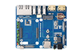
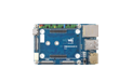 mini Base A |
×1 | √ | M.2 M | 2.0×4 | ×1 | ×2 | ×2 | 5V | 5V | mini size | ||
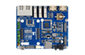
mini Base B |
×1 | √ | M.2 M | 2.0×4 | ×1 | ×2 | ×2 | √ | 5V | 5V | mini size | |
 mini Base C |
×1 | √ | M.2 M | 2.0×2 | ×1 | ×2 | √ | 5V | 5V | Dedicated 40PIN LCD Connector | ||
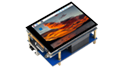 Touch screen |
×1 | M.2 M | 2.0×4 | ×1 | ×1 | 5V | IPS screen | |||||
 Mini Dual Gigabit |
×2 | √ | 2.0×1 | 5V SH1.0 | 5V | dual ETH | ||||||
 Binocular camera |
×1 | √ | M.2 M | 2.0×4 | ×2 | 5V | dual 8MP cameras |
|||||
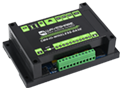
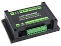
 4CH RS485 |
×1 | 2.0×2 | ×1 | ×2 | ×1 | 5V | 7-36V | dual ETH | ||||
 WIFI6 DUAL ETH |
×1 | √ | M.2 E | 2.0×3 | ×1 | ×2 | ×2 | ×1 | 5/12V | 7-36V | WIFI6 dual ETH | |
 Dual Gigabit ETH |
×2 | √ | 3.0×3 | ×1 | ×2 | ×2 | √ | 5/12V | 7-36V | |||
 IoT Dual Gigabit ETH |
×2 | √ | 3.0×2 | ×1 | ×2 | ×2 | √ | 5/12V | 5V | 5G/4G support | ||
 IoT Base |
√ | ×1 | Gen2×1 | 2.0×2 | ×2 | ×2 | ×2 | √ | 5/12V | 7-36V | 5G/4G support RS232 RS485 ADC |
|
 PoE Base (B) |
√ | ×1 | √ | Gen2×1 | 2.0×4 | ×2 | ×2 | ×2 | √ | 5/12V | 5V | RS232 RS485 |
 PoE UPS Base |
√ | ×1 | √ | M.2 M | 2.0×4 | ×1 | ×2 | ×2 | √ | 5/12V | 7-36V | UPS |
 PoE Base |
√ | ×1 | √ | 3.0×4 | ×2 | ×2 | ×2 | √ | 5/12V | 7-36V | ||
 Raspberry Pi official |
② | ×1 | √ | Gen2×1 | 2.0×4 | ×2 | ×2 | ×2 | √ | 12V | 12V | |
 Wireless base |
×1 | M.2 B / Mini-PCIe |
2.0×3 | ×1 | ×1 | √ | 5/12V | 5V or 7-36V |
5G/4G support RS485 CAN rail-mount |
|||
 UPS Wireless base |
×1 | M.2 B | 2.0×3 | ×1 | ×1 | √ | 5/12V | 5V or 7-36V |
With UPS 5G/4G support RS485 CAN rail-mount |
|||
 NAS Mini Computer |
×2 | √ | M.2 M×2/ Mini-PCIe |
3.0×2 | ×2 | ×2 | √ | 5V | dual M.2 M KEY slots | |||
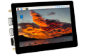 5″ touch screen |
② | ×1 | √ | M.2 M | 2.0×4 | ×1 | ×2 | √ | 5/12V | 5V | ||
 7″ all-in-one |
×1 | M.2 M | 2.0×4 | used | ×1 | used | √ | 5/12V used |
7-36V | touch screen camera speaker |
||
 13.3″ all-in-one |
×1 | 2.0×2 | 12V | HD touch screen | ||||||||
 13.3″ Magic Mirror |
×1 | 2.0×2 | 12V | HD screen, Speech Assistant |
||||||||
| Note | ① USB 3.0 is equivalent to USB 3.2 Gen1 ② There's PoE header only on the Raspberry Pi official IO board without PoE circuit, that means additional PoE module is required for the official IO board to enable PoE feature. Unless otherwise specified, the PoE feature here stands for integrating 802.3af-compliant PoE circuit (5V/2.5A). |
|||||||||||
Resources & Services
Wiki: Compute-Module-4
Weight: 0.107 kg
Quick Overview
- Compute Module 4 IO Board x1