Details
R7FA4 PLUS A Development Board, Based on R7FA4M1AB3CFM, Compatible with Arduino UNO R4 Minima
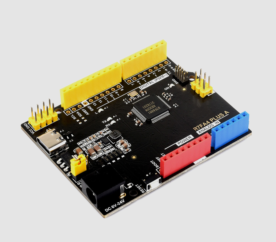
R7FA4 PLUS A Development Board
Enhanced version of Arduino UNO R4 Minima
Based on R7FA4M1AB3CFM, Compatible with Arduino UNO R4 Minima
Product Parameters Comparison
| Model | 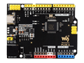 R7FA4 PLUS A |  R7FA4 PLUS B |  ESP32-S3-Nano |
|---|---|---|---|
| Microcontroller | R7FA4 (32-bit ARM Cortex-M4) | R7FA4 (32-bit ARM Cortex-M4) | ESP32-S3R8 (Dual-core 32-bit Xtensa LX7) |
| ESP32-S3FN8 (Dual-core 32-bit Xtensa LX7) | |||
| Clock Frequency | R7FA4: 48MHz | R7FA4: 48MHz | ESP32-S3R8: 240MHz |
| ESP32-S3FN8: 240MHz | |||
| Storage | R7FA4: 256kB Flash, 32kB RAM | R7FA4: 256kB Flash, 32kB RAM | ESP32-S3R8: 384kB ROM, 512kB RAM, 16MB Flash, 8MB PSRAM |
| ESP32-S3FN8: 384kB ROM, 512kB RAM, 8MB Flash | |||
| Wireless communication | None | 2.4GHz WiFi + Bluetooth LE | |
| Operating voltage | Options for 5V/3.3V, support more shields | 3.3V | |
| Power input | 6~24V | 6~21V | |
| Reset button | Lateral, easier to use when connecting with shield | Vertical | |
| IO pin Output current | 8mA | 40mA | |
| Digital pins | 14 | 14 | |
| Analog pins | 6 | 8 | |
| DAC | 2 | None | |
| PWM | 6 | 5 | |
| UART | 1 | 2 | |
| I2C | 1 | 1 | |
| SPI | 1 | 1 | |
| CAN | 1 | None | |
| DC jack | Low profile, shields won't be blocked anymore while connecting | None | |
| power output header | Provides 5V OR 3.3V power output and common-grounding with other boards | None | |
| 5V power output | Up to 2000mA Max, features higher driving capability | 1000mA Max | |
| experimental board | Support, solder pad is provided for DIY interfaces to connect with experimental board | Support | |
Connecting With Waveshare Shields
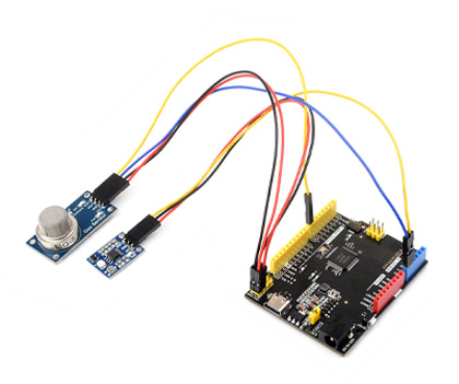
Connecting With Sorts Of Sensors
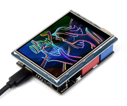
Connecting With 2.8inch TFT Touch Shield
* for reference only, please refer to the Package Content for detailed part list
What's On Board
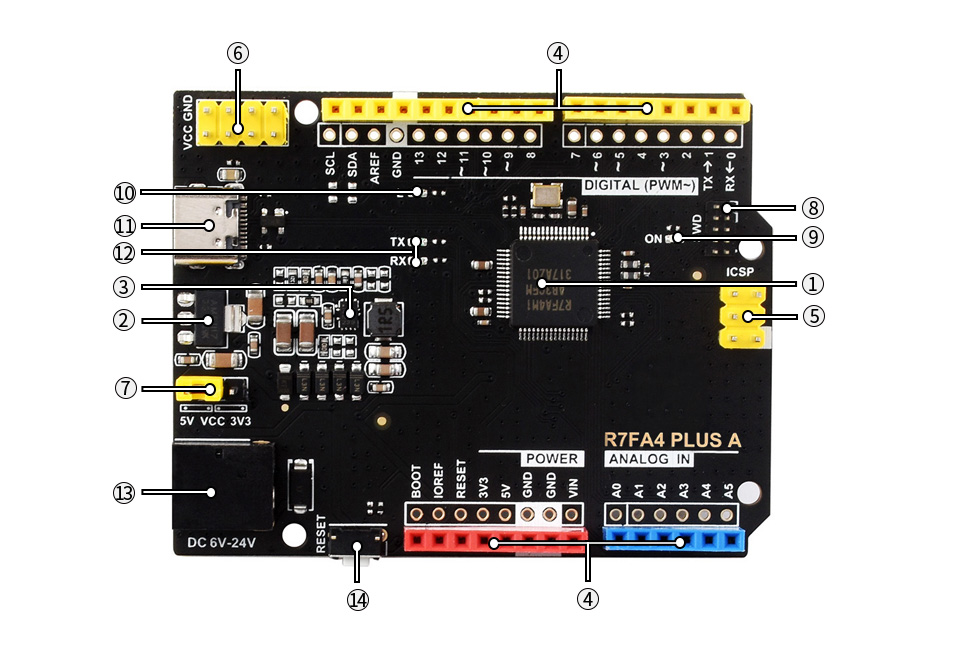
- R7FA4M1AB3CFM
- AMS1117-3.3
3.3V voltage regulator - MP8759
5V voltage regulator - Arduino interface
compatible with standard Arduino interface, adapting 2.54 pitch solder pad, can be directly connected to experimental board - ICSP interface
- Power output header
3.3V OR 5V, voltage level configured by the onboard power configuration switch, used as power output and common-grounding with other boards
- Power configuration
for configuring R7FA4 PLUS A operating voltage - SWD indicator
- Power indicator
- User LED
- USB Type-C connector
for uploading program OR serial port debugging - Serial port RX/TX indicators
- DC input
6V ~ 24V - Reset button
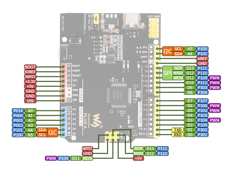
Pinout definition
Outline dimensions
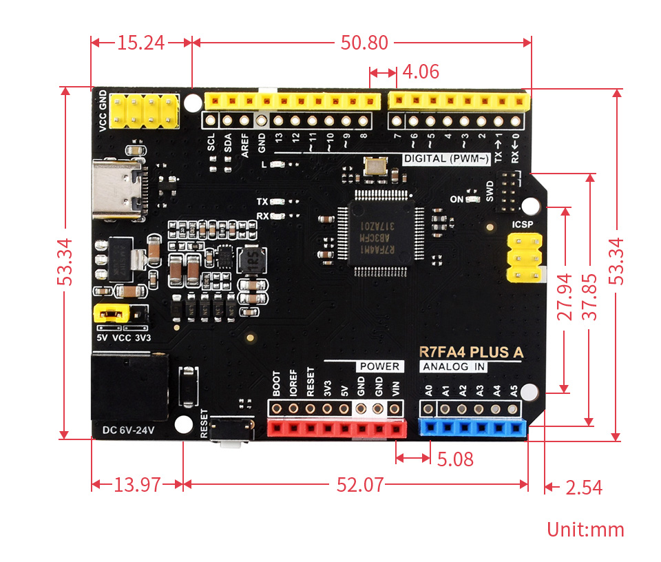

Weight: 0.047 kg
Quick Overview
- R7FA4 PLUS A x1
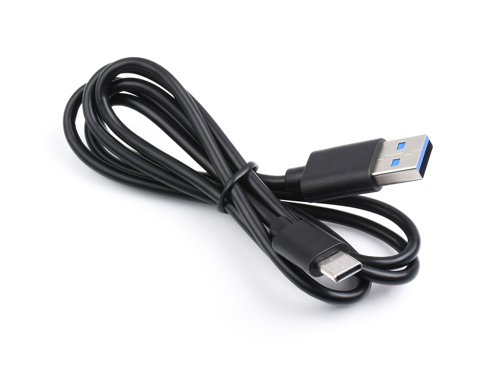
- USB Type-A to Type-C cable x1
1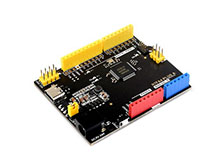
2