
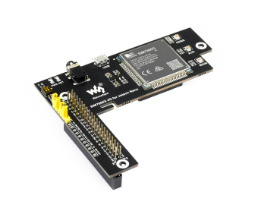
SIM7600E-H 4G HAT
| ||
| ||
| ||
| ||


Overview
Features
- 40PIN GPIO extension header for connecting Jetson Nano.
- Supports dial-up, telephone calls, SMS, mail, TCP, UDP, DTMF, HTTP, FTP, etc.
- Supports GPS, BeiDou, Glonass, and LBS base station positioning.
- Onboard USB interface, to test AT Commands, get GPS positioning data, and so on.
- Breakout UART control pins, to connect with host boards like Arduino/STM32.
- Onboard CP2102 USB to UART converter, for serial debugging.
- SIM card slot, supports 1.8V/3V SIM card.
- Onboard TF card slot, which can be used to store files, text messages, and other data.
- Onboard audio jack and audio decoder chip, for making telephone calls.
- 2 x LED indicators, easy to monitor the working status.
- Onboard voltage translator, the operating voltage can be configured to 3.3V or 5V via jumper.
- Baudrate: 300bps ~ 4Mbps (default: 115200bps)
- Autobauding baudrate: 9600bps ~ 115200bps.
- Comes with online resources and manuals (example demos such as Raspberry/Jetson Nano/Arduino/STM32).
Onboard Resources


Video
Specification
| Product | SIM7600CE-CNSE | SIM7600CE-T | SIM7600E | SIM7600E-H* | SIM7600A-H* | SIM7600G-H | |
|---|---|---|---|---|---|---|---|
| Working Frequency | |||||||
| LTE 4G | LTE-TDD B38/B39/B40/B41 LTE-FDD B1/B3/B5/B8 |
LTE-FDD B1/B3/B5/B7/B8/B20 LTE-TDD B38/B40/B41 |
LTE-FDD B2/B4/B12 |
LTE-TDD B34/B38/B39/B40/B41 LTE-FDD: B1/B2/B3/B4/B5/B7 | |||
| 3G | UMTS/HSDPA/HSPA+ B1/B8 TD-SCDMA B34/B39 |
UMTS/HSPA+ B1/B5/B8 |
UMTS/HSPA+ B2/B5 |
UMTS/HSDPA/HSPA+ B1/B2/B4/B5/B6/B8/B19 | |||
| 2G | GSM/GPRS/EDGE 900/1800 MHz |
not support | GSM/GPRS/EDGE 850/900/1800/1900MHz | ||||
| GNSS | not support | GPS/Beidou/GLONASS/GALILEO/QZSS | |||||
| Data Transmission | |||||||
| LTE Cat-4 |
150Mbps(DL)/50Mbps(UL) | not support | 150Mbps(DL)/50Mbps(UL) | ||||
| LTE Cat-1 | not support | 10Mbps(DL) /5Mbps(UL) |
not support | ||||
| 3G (HSPA+) | 42Mbps(DL)/5.76Mbps(UL) | ||||||
| 2G (EDGE) | 236.8Kbps(DL)/236.8Kbps(UL) | not support | 236.8Kbps(DL)/236.8Kbps(UL) | ||||
| 2G (GPRS) | 85.6Kbps(DL)/85.6Kbps(UL) | not support | 85.6Kbps(DL)/85.6Kbps(UL) | ||||
| Software Features | |||||||
| Network Protocol | TCP/IP/IPV4/IPV6/Multi-PDP/FTP/FTPS/HTTP/HTTPS/DNS | ||||||
| Internet Access | PPP/NDIS/RNDIS | ||||||
| USB Driver | Windows XP/7/8/10, Linux (RPi Raspbian System driver free) | ||||||
| Hardware Interface | |||||||
| SIM Card Slot | Both are supported, compatible with 1.8V and 3V SIM cards | ||||||
| UART Interface | Both are supported, the serial port sends and receives AT commands, and is compatible with 3.3V/5V working level | ||||||
| USB Interface | Both are supported and can be used to test AT commands, obtain GPS positioning information, upgrade firmware, etc. | ||||||
| USB to UART | Both are supported and can be used for serial port debugging or logging in to Raspberry Pi | ||||||
| Audio Port | Both are supported and can be used for voice operations such as making calls | ||||||
| TF Card Slot | Support, can be used to store files, text messages, and other data | Not Support | Support | ||||
| Antenna Connector | LTE main antenna | LTE Main Antenna + LTE Diversity Antenna + GNSS Antenna | |||||
| Application Scenarios | |||||||
| Applicable Area | China | Europe/Southeast Asia/West Asia/Africa /China/Korea |
North America | Used globally | |||
| Typical Applications | Medical and health, smart payment, public network intercom, environmental monitoring, energy monitoring, fleet management, smart industry, smart agriculture | ||||||
Quick Test
Hardware Preparation
- In addition to the micro USB cable, LTE antenna, and GPS antenna, users need to prepare the following items before using the module:
A 4G SIM card (no downtime and GPRS enabled);
A headphone cable with a microphone (optional);
A TF card (optional);
Hardware Connection
- When powering off, insert the activated 4G SIM card, and TF card (optional), insert the headphone cable with microphone (optional), and then connect the USB cable to the computer.
- Hardware connection diagram:

- Back Connection Diagram:

Hardware Configuration of the New Version
In the second half of 2021, the SIM7600 series boards will be switched to new versions for shipment. The old and new versions can be used normally and stably. Compared with the old version, the new version has the following changes:

- 1) Newly added 330uF electrolytic capacitor (Stronger voltage stabilization ability).
- 2) Newly added PWR and Flightmode pin jumpers (Automatic power-on function can be set, and the IO port can be customized to control the switch and Flight mode).
- 3) Add solderable pads for VCCIO.(when used with Raspberry Pi, the SIM7600X 4G HAT is soldered at a 3.3V working level by default; if you need to use 5V working-level MCU, you can change it to 5V by yourself).
- 4) Add solderable pads for the module USB. (if you don't want to use a USB adapter cable, you can solder them to the corresponding USB solder joints at the bottom of the Raspberry Pi through some flying cables. This operation should be used with caution by non-professionals).
- 5) The power management IC was changed from MP1482 to SPX29302.
- 6) The silkscreen naming is changed from "WPI naming" to "BCM naming".
- 7) Fine-tuning the layout.
- 8) Add new solder joints for the module Boot to flash the firmware forcibly. Short-circuit the two pads can enter the forced firmware flashing mode. (Only used when the firmware cannot be flashed normally).
Description of turning on/off the HAT for the New Version
- In the new version, PWR and 3V3 are short-circuited by default, so the HAT is turned on automatically after connecting to the power supply.
- If you need to use the PWRKEY button to turn on/off the HAT, please remove the jumper cap between PWR and 3V3:
- If you want to use the Raspberry Pi to turn on/off, please set the jumper cap between PWR and D6:

- The old version is manually switched on and off by default. If you need to set it to power on automatically, you need to short the PWR and GND pins together through the DuPont wire as shown below:

- Manual power on/off: Support the "PWRKEY button" or "Raspberry Pi D6 pin" to control the power on/off.
- "PWRKEY button": Press the PWRKEY button for about 1 second, wait for about 10 seconds, and see the NET light start to blink once every second, then the module starts to work; if you want to shut down, press and hold PWRKEY button for 3~5s to shut down, and the NET light will be off.
- "Raspberry Pi D6 pin" control switch: you need to control the D6 pin output high and low levels through the code to achieve the switch.
- Power on automatically: After the module is connected to the device, it will automatically power on.
- This method can not be turned off, if you need to reduce power consumption, you can turn off the RF or enter the flight mode.
Flight mode description of the New Version
- The new version of the HAT doesn't turn on the Flight mode by default:
- If you need to control the Flight mode through the Raspberry Pi pins, set the jumper cap between Flight and D4:

Net Indicator Working Status

Software Envirnment
- Test environment: Windows operating system
- Test software: SIM7600 serial port debugging assistant
- Driver file: SIM7600X driver
Install Driver
1. Download Driver: SIM7600X driver
2. Insert the 4G HAT into the Windows computer as shown in the hardware connection diagram above (the Windows 10 operating system is used as an example below).
3. Make sure the module has been powered on normally: refer to the previous chapter "Switching on and off the module".
4. Unzip the driver file --> Double-click the exe driver file with the left mouse button --> Select the installation path --> NEXT --> Wait for the installation to complete --> Restart the computer --> Complete the driver installation.
.jpg)
.png)
.png)
.png)
.png)
.png)
- After installation, all the devices should be recognized normally as below:
.png)
- After installation, all the devices should be recognized normally as below:

Common AT Command
- SIM7600X module supports AT command control, some basic AT commands are shown in the table below:
(For the complete AT command set, please refer to: For more AT commands, please refer to: SIM7600X series AT command set)
| Command | Description | Return |
|---|---|---|
| AT | AT Test Command | OK |
| ATE | ATE1 set echo ATE0 close echo |
OK |
| AT+CGMI | Query module manufacturer | OK |
| AT+CGMM | Query module model | OK |
| AT+CGSN | Query product serial number | OK |
| AT+CSUB | Query module version and chip | OK |
| AT+CGMR | Query the firmware version serial number | OK |
| AT+IPREX | Set the module hardware serial port baud rate | +IPREX: OK |
| AT+CRESET | Reset module | OK |
| AT+CSQ | Network signal quality query, return signal value | +CSQ: 17,99 OK |
| AT+CPIN? | Query the status of the SIM card and return READY, indicating that the SIM card can be recognized normally | +CPIN: READY |
| AT+COPS? | Query the current operator, the operator information will be returned after normal networking | +COPS: OK |
| AT+CREG? | Query network registration status | +CREG: OK |
| AT+CPSI? | Query UE system information | |
| AT+CNMP? | Network mode selection command: 2: Automatic 13: GSM only 38: LTE only 48: Any modes but LTE ... .... |
OK |
AT command sending and receiving test
- Download serial debugging assistant: SIM7600 serial debugging assistant
- Open the device manager, find the port number corresponding to AT Port; then open the sscom software, select the corresponding port and baud rate, check "Add carriage return and line feed"; click the sscom "Extension" button and pull out the preset It is best to open the serial port and send the corresponding AT command to test. The test screenshot is shown below:

Dailing up
PC Windows
- Usually, when we use the Windows 10 operating system, make sure that the hardware and software drivers are installed. After the module is powered on, the PWR light is on normally, the NET light is flashing normally, and it will automatically connect to the Internet. If the Internet cannot be automatically connected, we can also use NDIS or PPPD to connect to the Internet.
NDIS
The steps for Windows NDIS dialing are as follows:
1. Open the SIM7600 AT port, and send the command (if using SSCOM to generate AT command, you must check "Enter"):
AT$QCRMCALL=1,1 //must press "Enter"

2. At this point, the NDIS dialing takes effect, and the computer can connect to the network.
PPPD


Raspbian

- Insert the module into the Raspberry Pi, and connect the USB interface to the USB port of the Raspberry Pi, turn it on, and the hardware is as shown below:
- Refer to "Raspberry Pi initialization settings" below, The Raspberry Pi does the initial setup.
- For dial-up Internet access, refer to the following operation video (for dial-up Internet access, it is recommended to use a USB interface connection, which is faster):
Raspberry Pi RNDIS dial-up Internet access
NDIS dial-up and self-starting
PPPD dial-up
- After dialing up the Internet, if the DNS cannot be resolved and the Internet cannot be accessed, you can add the command:
route add -net 0.0.0.0 usb0
route add -net 0.0.0.0 wwan0
route add -net 0.0.0.0 ppp0
GNSS
GNSS Position
- Plug in the GPS antenna, and place the receiver in an open space (note that it cannot be tested in rainy weather). It takes about 1 minute to receive the positioning signal after power-on;

- AT Command
AT+CGPS=1 //Open GPS
AT+CGPSINFO //Print GPS information to the serial port
AT+CGPS=0 //close GPS
- SSCOM Software Test:

TCP/IP Network Data
GPRS debugging requires a SIM card with the GPRS networking function enabled.
We take accessing a mobile SIM card as an example:
- Correctly install the mobile phone card (the GPRS networking function must be enabled), the GSM antenna, and connect the USB cable to the computer;
- Press the PWR key to start the module and wait for more than ten seconds;
- Observe whether the indicator light is normal, the PWR indicator is always on, and the NET indicator is flashing.
Set up a local computer virtual server
The virtual server defines the mapping relationship between the WAN service port and the LAN network server. All-access to the WAN service port will be relocated to the LAN network server specified by the IP address. (Please refer to your router's corresponding manufacturer's manual).
Use a browser to log in to the router management interface (please refer to your router manual for the specific address).
Set the port number: 2317 (it does not conflict with the existing port number. In this example, it is set to 2317).
Set the intranet IP of the computer (the IP obtained by the computer in the local area network can be run CMD on the local machine, enter the command line prompt, enter ipconfig to view the IPv4 address, the intranet IP of the computer in this example is 192.168.1.168), as shown in the following figure:

Set up GPRS
AT+CGDCONT=1,"IP","CMNET" //Set APN
AT+CSQ //Query the network signal quality, the first parameter is the maximum network signal quality is 31, the larger the value, the stronger the network signal
AT+CREG? //Query the network registration status, where the second parameter is 1, it means the registration has been successful
AT+CIPMODE=1 //Set TCP/IP mode
AT+CSOCKSETPN=1 //Select TCP/IP application mode
AT+CIPMODE=0 //Select TCP/IP application mode
AT+NETOPEN //Open mode
AT+CIPOPEN=0,"TCP","113.81.233.65",2317 //Set TCP, IP, and port number to establish TCP/IP connection
AT+CIPSEND=0,9, //To specify to send 9 characters of data, return > to start sending 9 characters of content
AT+CIPCLOSE=0, //Close the TCP connection
AT+NETCLOSE, //Close the network
The operation steps are shown in the following figure:

TF Card Debugging
1. Insert the TF card when the power is off (press the pop-up), follow the normal boot steps, and select the port number:

2. Select the TF card directory as the current directory:
AT+FSCD=D: //Select TF card path
+FSCD: D:/
OK
AT+FSLS //View subdirectories
+FSLS: SUBDIRECTORIES:
overlays
MyDir
System Volume Information
...
...
OK

3. Create a folder with content on the TF card. Use the statement to set the MyDir folder in the root directory, create a t1.txt file in the folder, and write the content test content at the same time.
AT+CFTRANRX="D:/MyDir/t1.txt",12 //File name
>test content //Content
OK

4. Open TF Card:


For more information, please refer to SIM7600X AT Commands.
Phone Call
Dail
- Refer to the "Hardware Configuration" chapter to connect the LTE antenna, SIM card (the phone function must be enabled), and the headset cable with microphone, and the module is turned on.
- Common commands for making calls:
| AT+CNUM | Query the phone number (not all SIM cards support this command) | +CNUM OK |
| AT+CSDVC | AT+CSDVC=1: switch to headphone output AT+CSDVC=3: switch to speaker output |
OK |
| AT+CLVL=? | Query volume range | OK |
| AT+CLVL=2 | Set volume to 2 | OK |
| ATD<phone_number>; | ATD10086; : Dial the customer service number of Mobile 10086 | OK |
| AT+CHUP | hang up | OK |
| AT+CLIP=1 | Set Caller ID | OK |
| ATA | Answer the call | OK |
- The detailed operation screenshots are as follows:

【Note】: When using the SSCOM serial port assistant to send and receive AT commands, you must check "Enter".
Voice output mode and volume adjustment
AT+CSDVC=1 //Switch to headset
AT+CSDVC =3 //Switch to speaker
AT+CLVL =? //Query the volume range, return +CLVL: (0-5) //Indicates that the volume is adjustable from 0 to 5
AT+CLVL=2 //Set the volume to 2, return OK
Answer the call
Incoming call serial display: RING
send "ATA" // answer the call
Send "AT+CHUP" //hang up
Audio parameter debugging
AT+CACDBFN=?
+CACDBFN: (Handset_cal.acdb,Handset_tianmai.acdb) // It is recommended to consider setting this set of parameters
OK
A. In the initialization stage of the module startup, before making a call, add the following:
AT^PWRCTL=0,1,3 // Mainly improve TDD noise effect
OK
B. The module is in the process of establishing a voice call:
VOICE CALL:BEGIN // The module call is established and executed to improve the call effect
AT+CECM=1 //Echo suppression processing
OK
AT+CECH=0x500 //Improve the volume effect of the mobile phone
OK
SMS sending and receiving
Send English SMS
1. Install the SIM card and LTE antenna, connect the module's USB interface to the computer with a USB cable, and turn on the module;
2. Observe whether the indicator light is normal, the PWR indicator is always on, and the NET indicator is flashing;
3. Set the local SMS center: AT+CSCA="+8613800755500"+Enter, return OK.
4. AT+CMGF=1: Set the SMS mode to TEXT;
5. AT+CMGS=" phone number "<Enter>, set the recipient's mobile phone number, and then return: ">", send the desired content, such as "Send message test!", no need to enter at the end, after editing the text message Send 1A to send information in hexadecimal format (1A is the key value of "CTRL+Z", which is used to tell the module to execute the sending operation, or 1B or "ESC" to cancel the operation), after successful sending, the module returns + CMGS: 15 Confirmation that the transmission was successful. As shown below.

Receive English SMS
1. Send a message on the phone: "This is a receive test for SIM7600X!" to the test module.
2. When receiving the information, the serial port will report the information, "SM", 20, which means there are 20 pieces of information in the SM, and the message just sent is the 20th piece of information.
3. Read information: AT+CMGR=20 to read the 20th information (AT+CMGL="ALL" to read all information).
4. Delete information: AT+CMGD=20, as shown below:
5. Convert the displayed information to text through a code converter.

RPi Demo
Hardware Connection

SIM7600X 4G HAT has onboard Raspberry Pi GPIO interface, which can be directly inserted into various versions of Raspberry Pi; the following table shows the connection between Raspberry Pi pins and module pins (Raspberry Pi 3rd Generation B+):
| SIM7600X 4G HAT | Raspberry Pi |
|---|---|
| 5V | 5V |
| GND | GND |
| RXD | TXD (corresponding to 14 of BCM) |
| TXD | RXD (corresponding to 15 of BCM) |
| PWR | P22 (corresponding to P6 of BCM) |
| FLIGHTMODE | P7 (corresponding to P4 of BCM), enter flight mode when pulled high |
* FLIGHTMODE is wired to pull up and will enter into flight mode.
Raspberry Pi serial port configuration
Since the Raspberry Pi serial port is used for terminal debugging by default, if you need to use the serial port, you need to modify the Raspberry Pi settings. Execute the following command to enter the Raspberry Pi configuration:
sudo raspi-config
Select Interfacing Options -> Serial -> no -> yes to disable serial debugging.

Open the /boot/config.txt file, and find the following configuration statement to enable the serial port, if not, add it at the end of the file:
enable_uart=1
Restart to take effect.
Raspberry Pi minicom serial port debugging
1. Insert the module into the Raspberry Pi.
2. Install minicom, which is a serial debugging tool for the Linux platform:
sudo apt-get install minicom
3. Execute minicom -D /dev/ttyS0 (ttyS0 is the serial port of Raspberry Pi 3B/3B+/4B).
The default baud rate is 115200.
Raspberry Pi 5/2B/zero, the user serial device number is ttyAMA0, and the Raspberry Pi 3B/3B+/4B serial device number is ttyS0.
4. Take the AT synchronization test as an example, and send relevant commands, as shown in the following figure: 
* minicom can enter setting mode by pressing Ctrl+A, then Z, and select X to exit.
5. Raspberry Pi 5 configures the ttyS0 serial port:
- Edit config.txt file:
sudo nano /boot/config.txt
- Add the following and the statement at the end.
dtoverlay=disable-bt
- You can see ttyS0 after restarting.
Sample Demo
1. Insert the module into the Raspberry Pi.
2. Download the sample demo to the /home/pi/ path:
wget https://files.waveshare.com/upload/2/29/SIM7600X-4G-HAT-Demo.7z
sudo apt-get install p7zip-full
7z x SIM7600X-4G-HAT-Demo.7z -r -o/home/pi
sudo chmod 777 -R /home/pi/SIM7600X-4G-HAT-Demo
3. Go to the bcm2835 directory, compile, and install it.
chmod +x configure && ./configure && sudo make && sudo make install
Note: If there is a problem with the compilation, please refer to the instructions in the FAQ.
4. Go to the corresponding instance directory, compile, and run the demo. The relevant instructions are as follows (take the PhoneCall demo as an example):
sudo make clean //Clear the original executable file
sudo make //recompile
sudo ./PhoneCall //Run the demo
Use a combination of the above commands:
sudo make clean && sudo make && sudo ./PhoneCall
PHONECALL Call Demo

SMS Text Message Sending and Receiving Demo

GPS Positioning Demo

TCP Network Communication Demo

FTP Download and Upload Demos

Arduino Demo
Hardware Connection
Hardware connection to the development board UNO PLUS/Arduino UNO:
| SIM7600X 4G HAT | UNO PLUS/Arduino UNO |
|---|---|
| 5V | 5V |
| GND | GND |
| TXD | 0 (RX) |
| RXD | 1 (TX) |
| PWR | 2 |
Install Arduino library
Download the decompression sample demo.
Copy the Waveshare_SIM7600X_Arduino_Library folder to the Library directory under the Arduino IDE installation path.
Open Arduino IDE --> File --> Examples --> Waveshare SIM7600X, and then choose to run the corresponding example demo:

Sample Demo
PHONECALL Call Demo

SMS Text Message Sending and Receiving Demo

GPS Positioning Demo

TCP Network Communication Demo

FTP Download and Upload Demo

Jetson Nano Demo
Hardware Connections

Jetson Nano has an onboard RaspberryPi 40Pin GPIO interface, SIM7600X 4G HAT can be directly connected and used, and Jetson Nano's terminal access the serial port does not affect serial communication with SIM7600X 4G HAT (ie. Pin10 and Pin8).
| SIM7600X 4G HAT | Jetson Nano |
|---|---|
| 5V | 5V |
| GND | GND |
| TXD | 10 (Board encoding) |
| RXD | 8 (Board encoding) |
| PWR | 31 (Board code) |
Jetson Nano minicom serial port debugging

1. Connect the SIM7600X 4G HAT to the Jetson Nano, press the PWRKER button for three seconds, and then turn it on.
2. Use SERIAL to log in to the Jetson Nano terminal, install minicom, and enter:
sudo apt-get install minicom
3. Run minicom to debug the serial port, and enter in the terminal.
sudo minicom -D /dev/ttyTHS1 -b 115200
4. Send the AT command to test, press the PWRKEY button for three seconds to start the shutdown, exit the minicom and press Ctrl+A, then X, and finally press ENTER.
Python Demos

After installing the library:
sudo apt-get install python3-pip
sudo pip3 install pyserial
sudo apt-get install p7zip
Use the wget tool to download the source code to the specified folder of Jetson Nano, and copy the following command:
mkdir -p ~/Documents/SIM7600X_4G_HAT
wget -P ~/Documents/SIM7600X_4G_HAT/ https://files.waveshare.com/upload/2/29/SIM7600X-4G-HAT-Demo.7z
Enter the directory where the source code was just created and downloaded, and use the p7zip tool to unzip it to the current directory.
cd ~/Documents/SIM7600X_4G_HAT/
sudo p7zip --uncompress SIM7600X-4G-HAT-Demo.7z
AT

SIM7600X_4G_HAT is connected to Jetson Nano, connected to the antenna, the demo uses the software to power on and off, there is no need to press the button to power on and off, and when you exit, press Ctrl+C to power off the software. Enter the Jetson Nano/AT directory and execute the command:
cd ~/Documents/SIM7600X_4G_HAT/Jetson\ nano/AT/
sudo python3 AT.py
GPS

SIM7600X_4G_HAT is connected to the Jetson Nano and GNSS antenna. The demo uses software to power on and off. There is no need to press the button to power on and off. When exiting, press Ctrl+C to power off the software. Enter the Jetson Nano/GPS directory and execute the command:
cd ~/Documents/SIM7600X_4G_HAT/Jetson\ nano/GPS/
sudo python3 GPS.py
PhoneCall
SIM7600X_4G_HAT is connected to Jetson Nano, the main antenna, and the earphone. The demo uses software to power on and off, no need to press the button to switch on and off. This demo uses the mobile card to automatically dial 10086. Press Ctrl+C when exiting, and the software will start to Shut down. Enter the Jetson Nano/PhoneCall directory and execute the command:
cd ~/Documents/SIM7600X_4G_HAT/Jetson\ nano/PhoneCall/
sudo python3 PhoneCall.py

SMS

The SIM7600X_4G_HAT is connected to the Jetson Nano and the main antenna. The demo uses the software to turn it on and off, and there is no need to press the button to turn it on and off. This demo will automatically shut down the software after sending the information www.waveshare.com to the specified number. When users use SMS demos, they must first use tools such as vim to change the number in line 10 of the SMS.py file, replace * with a number, and keep the ' symbol.
Enter the Jetson Nano/SMS directory and execute the command:
cd ~/Documents/SIM7600X_4G_HAT/Jetson\ nano/SMS/
sudo python3 SMS.py
TCP
The SIM7600X_4G_HAT is connected to the Jetson Nano and the main antenna. The demo uses the software to turn it on and off, and there is no need to press the button to turn it on and off.
Enter the Jetson Nano/TCP directory and execute the command:
cd ~/Documents/SIM7600X_4G_HAT/Jetson\ nano/TCP/
sudo python3 TCP.py

More sample demos are continuously updated...
Resource
Documentation
Demo
Software
- SIM7600 Driver
- CP2102 driver
- SIM7600 Serial Debug Assistant
- GPS Debug Tool
- TCP Test Tool
- Xshell
- VLC media player
- Unicode Conversion Software
Datasheet
Certificate
Video
FAQ
- SIM7600X 4G HAT supports Standard SIM card.
- SIM7600X 4G Dongle supports Nano SIM card.

In this case, it may be that you have not successfully connected to the network, you can follow the steps below to troubleshoot:
1. First check the hardware connection:
- Check if the MAIN antenna is well connected;
- Whether the connected SIM card can call and surf the Internet normally on mobile phones and other devices:
- It is recommended to replace the SIM cards of different operators. Under the comparison test, the network frequency bands and base station layouts supported by different operators are different. Changing the SIM card can also eliminate problems such as card arrears
2. After confirming that there is no problem with the hardware, the software can use these instructions:
- Check whether the sim card is in good contact: AT+CPIN?
- Check whether RF is turned on (flight mode is turned off): AT+CFUN?
- Check if the network mode setting is correct: AT+CNMP?
- Check the signal quality of the current environment: AT+CSQ
- Check the operator's access situation: AT+COPS?
- Check the connection status: AT+CPSI?
- Check the operator's access situation: AT+CGDCONT?
- Check the connection status: AT+SIMCOMATI
- Check whether it is successfully registered to the network: AT+CGREG?


{{{5}}}
{{{5}}}
{{{5}}}
Restart SIM7600E-H after sending the following commands:
AT+CGPSNMEAPORTCFG=3
AT+CGPSNMEA=197119
AT+CGPSINFOCFG=10,31
 AT+CLBS=? //View the range of parameters that can be set
 AT+CNETSTART//Open the network; if it fails to open the network, you can use the command AT+CNETSTOP to close and then open
 AT+CLBS=1 //Get the current latitude and longitude
 AT+CLBS=2 //Get the detailed address
{{{5}}}
This problem is generally caused by poor contact between the SIM card and the SIM card socket of the module.
ATE1
{{{5}}}
Since the Raspberry Pi serial port is used for terminal debugging by default, if you need to use the serial port, you need to modify the Raspberry Pi settings. Execute the following command to enter the Raspberry Pi configuration:
sudo raspi-config
Select Interfacing Options ->Serial ->NO ->YES to disable serial debugging

Open the /boot/config.txt file, and find the following configuration statement to enable the serial port, if not, add it at the end of the file:
enable_uart=1Restart to take effect
{{{5}}}
It may be that the APN has not been obtained. Generally, the APN can be obtained automatically. In some areas (IoT card), it needs to be obtained manually. For example, it can be set by the following instructions:
AT+CGDCONT=1,"IP","Your_APN" //The APN of different operators is different, here the APN is changed to the corresponding operator, for example:
China Mobile APN: CMNET; China Unicom APN: 3GNET; China Telecom APN: CTNET

It can be set by the following commands:
AT+CGDCONT=1,"IPV6","APN" //Switch to IPV6, the APN of different operators is different, pay attention to distinguish the settings
AT+CGDCONT=1,"IP","APN" //Switch back to IPV4
- No APN is set, configure APN as described above.
- After being banned, high-traffic (real-name IoT) cards are bound by chance cards and can only be used on one device (Ministry of Industry and Information Technology, Ministry of Public Security, must be issued to operators); The operator checks the status of the card and unlocks it.
The VOLTE function can be turned on with the following command:
 at+voltesetting=1
 at+cnv=/nv/item_files/modem/mmode/ue_usage_setting,1,01,1
The VOLTE function can be turned off with the following command:
 at+voltesetting=0
 at+cnv=/nv/item_files/modem/mmode/ue_usage_setting,0,01,1
AT+CSCA="+8613800755500"
Command to add + Enter, return OK. Note: China Mobile's SMS service center number is +861380xxxx500, where xxxx is the long-distance telephone area code where you are located. The SMS center may be different from place to place. For details, you can query Baidu or call the customer service of China Mobile Unicom. This SMS center is Shenzhen (0755).
- Confirm that SIM7600X is registered to the network, and confirm that the SIM card can send and receive text messages normally on mobile phones and other devices;
- Set the correct SMS center number;
- Initialize SMS settings with the following commands:
AT+CSCS="IRA"
AT+CSMP=17,167,0,0
The AUX antenna can increase the downlink rate: The AUX antenna is also a diversity antenna, which plays the role of receiving signals, improves the signal reception capability, and works with the MAIN antenna to increase the downlink rate.

- Under normal circumstances, SIM7600X has been automatically dialed after receiving the Windows system, and there is no need to repeat dialing. Repeated dialing will return NO CARRIER
- If you still can't dial-up Internet access, please use the following command to change to Windows default dial-up Internet access mode
AT+CUSBPIDSWITCH=9001,1,1
- The display is turned off, and the mobile network is not enabled, you can ignore it and go online directly;
.png)
- You can also install the driver SIM7600X dial-up Driver to update the network card.
.png)
- The network card display is enabled after installing the driver.
.png)
- Generally, the default configuration of SIM7600 is to automatically select the network standard, and it is likely to choose 2G Internet access; if you need to force the use of 4G mode, you need to enter the following AT command configuration:
AT+CNMP=38 //Fixed 4G LTE, if there is no local 4G coverage, you may not be able to register to the network
.png)
- If 4G has been fixed, the speed is still not ideal, it may be a frequency band problem;
AT+CNBP? //Back up the current frequency band (the returned frequency band information can be copied to notepad, etc.)
AT+CNBP=0x0002000000400183,0x000001E000000000,0x0000000000000021 //After returning OK, measure the speed
AT+CNBP=0x0002000004400180,0x000001E000000000,0x000000000000003F //If the speed does not improve, try this

.png)
1. Pay attention to checking the device manager, the new device will be prompted during the upgrade process, and there will be no device driver during the first upgrade;
2. Pay attention to the USB cable. The speed of the USB cable is higher during the upgrade process. You need to choose a better-quality USB cable to avoid poor contact.
3. You need to run the upgrade tool with administrator privileges (SIM7500_SIM7600_QDL V1.41 only for Update)
4. Uninstall and reinstall the upgrade tool (SIM7500_SIM7600_QDL V1.41 only for Update)
5. For more operation details, please refer to this video: https://www.waveshare.net/wiki/SIM7600-Firmware-upgrade-Video
If the short message is stored in the SIM card, usually 50 is the upper limit. You can use the command: AT+CPMS? Make a query
- Gain: 9dbi ± 0.7dbi
- It is recommended to use the more convenient RNDIS dial
- Can burn the latest Raspberry Pi Raspbian system, reconfigure NDIS dial-up
- Or use the image that has been configured with the driver NDIS dial-up and start the Raspbian system image (the driver has been installed)
- Currently there is the driver source code of Android4-Android11, that is, the system version is Android4-Android11 only supported;
- Get the source code and SDK of the Android system of the target device (requires official image support), then add SIMCOM's Android system driver source code to the Android source code, and recompile (the compilation time varies from 1-10 hours, it is recommended to use a high-configuration PC operate);
- If the USB can be recognized, it means that the Android driver has been installed successfully. Set the module to 9011 mode or 9018 mode, and you can dial up to access the Internet;
- The steps to install the Android driver are cumbersome, and the operator is required to have certain Android system development experience and R&D capabilities.
The IP obtained by different dialing methods is different and has different characteristics. Please refer to the following table for details:

Below is a detailed description of the various dials:
- NDIS driver for Internet access (9001 mode)
This method must depend on the Linux system and is suitable for application scenarios that need to be developed using Linux network socket programming. After loading the driver into the kernel, connect the SIM7600 to the motherboard with a USB cable. After the SIM7600 is turned on, the wwan0 network can be recognized. port, you can access the Internet through this network port. The bottom layer of this method depends on the USB virtual serial port of SIM7600. This dial-up method can obtain the IP provided by the public operator, and the network speed is faster.
- RNDIS (9011 mode)
RNDIS refers to Remote NDIS. The implementation of RNDIS based on USB is TCP/IP over USB, which is to run TCP/IP on the USB device, making the USB device look like a network card. This method only needs simple configuration, the motherboard will recognize the USB0 network card, and quickly obtain the USB0 network card and module or the operator's IP network access; RNDIS network speed is relatively fast, which is one of the most commonly used dial-up methods.
- ECM (9018 mode)
These two are the "NDIS" standard under Linux. ECM is the abbreviation of the Ethernet Networking Control Model. ECM meets the requirements of the CDC on USB. The data call established through standard CDC-ECM is routed through the router, and the obtained IP address is a private IP such as 192.168; if the kernel supports this way, no additional driver is required. All data interacting with the module through the USB bus is constrained by relevant protocols and standards, and the module reaches the module through the USB hardware to complete the interaction with the Linux motherboard.
- PPP dial-up
This method must depend on the Linux system and is suitable for application scenarios that need to be developed using Linux network socket programming. After configuring and running the relevant scripts, connect the SIM7600 with a USB cable. After the SIM7600 is powered on, dial up the pppd script to identify it. To the ppp0 network port, you can access the Internet through this network port and obtain the operator's IP. The bottom layer of this method depends on the USB virtual serial port of SIM7600.
- AT command uses encapsulated TCP, MQTT, HTTP(S)
This method is suitable for microprocessors with limited resources, such as MCU, or for application scenarios with a relatively small amount of data, such as uploading sensor data to servers, cloud platforms, etc. through http(s), MQTT. If the network application is not complicated and the amount of data is relatively small (such as transmitting sensor data to the server and receiving control commands from the server), the function can be quickly used by using AT commands.


The general operation is: download the sample program, after decompression, rename the c folder under the Raspberry folder to SIM7600X, then copy the entire SIM7600X folder to the Raspberry Pi /home/pi directory, and enter the command line to /home/pi /SIM7600X directory, and then execute the chmod 777 sim7600_4G_hat_init command.


Restart SIM7600E-H after sending the following commands:
AT+CGPSNMEAPORTCFG=3
AT+CGPSNMEA=197119
AT+CGPSINFOCFG=10,31
AT+CGPSAUTO=1
SIM7600G-H 4G HAT supports Raspberry Pi 4 Model B. Our most commonly used main control is Raspberry 4B.
{{{5}}}
The SIM7600x series doesn't support the MMS function.
{{{5}}}
The reset pin only allows the module to restart and reset a small number of functions.
Not all functions of the module can be reset.
In fact, it is similar to this command function:
AT+CRESET
Therefore, we did not lead out this pin, which has little effect.
{{{5}}}
Support
Technical Support
If you need technical support or have any feedback/review, please click the Submit Now button to submit a ticket, Our support team will check and reply to you within 1 to 2 working days. Please be patient as we make every effort to help you to resolve the issue.
Working Time: 9 AM - 6 PM GMT+8 (Monday to Friday)