
ROCK3 Model A
Overview
Introduction
- As a compact and powerful AI development board, ROCK3 Model A features quad-core 64-bit Cortex-A55, ARM G52 GPU, NPU, supports AI frameworks such as OpenGL, provides rich, optional RAM, eMMC flash and wireless modules.
Features
- Rockchip RK3568 Cortex-A55 (64 bit 2.0GHz Quad-Core)
- 2GB, 4GB or 8GB LPDDR4-3200 SDRAM memory
- Storage
- eMMC (16GB/32GB/64GB/128GB)
- μSD card (μSD card slot,Maximum support 128GB μSD card)
- M.2 SSD
- Support Gigabit Ethernet
- Optional Wireless Module A1 module, support 2.4G WIFI and 4.2 Bluetooth
- Support OpenGL ES 1.1/2.0/3.2,OpenCL 2.0,Vulkan 1.1
- Support 4K 60fps H.265/H.264/VP9 video decoding and 1080P 60fps H.265/H.264 video encoding
- USB 3.0 OTG x1 (Host/Device mode), USB 3.0 HOST x1 , USB 2.0 HOST x2
- HDMI interface (support 4K*2K@60)
- MicroSD card slot
- 3.5 mm Audio Jack
- 40PIN GPIO Interface
- CSI camera interface
- DSI Display Interface
- Power
- PD fast charger Type C PD2.0,9V/2A,12V/2A,15V/2A,20V/2A
- Qualcomm® QC fast charger:support QC 3.0/2.0 power supply,9V/2A,12V/1.5A
Install System
Download official images
- Radxa officially provides two versions of the system image for ROCK3 Model A, namely Debian Buster 10 and Ubuntu Server 20.04.
- You can download the new images from Radxa
Install Image on TF Card
Equipment Preparation
1. TF card reader.
2. at least 8 GB of TF card
Image Flashing
- To avoid errors in the process of flashing the image, you need to use Panasonic_SDFormatter-SD card formatting software before flashing the image.
- Pay attention when formatting, if you have another removable hard disk inserted into your computer, don't format the wrong drive.
1. Open Win32DiskImager-Image Flashing Software
2. Insert the TF card into the card reader, and then insert it into the computer
3. Choose the downloaded image document, click "写入" and wait

Install Image on EMMC
Equipment Preparation
- ROCK3 Model A motherboard
- EMMC module
- type A Dual Male USB3.0 Cable
- Jumper cap, tool for short circuit (pin header)
- Power adapter
Preparation


1.Download Rockchip micro-brush tool RKDevTool_Release-Brush Tool and DriverAssitant-RK Driver Assistant
2.Open RK DriverAssitant to install ROCK3 Model A USB driver, this process does not need to connect ROCK3 Model A, restart the computer after the installation is complete
3.Install the EMMC, if there is a TF card on the board, remove the TF card first
4.Use jumper caps and pin headers to short-circuit the ROCK3 Model A pins, as shown in the figure, counting from left to right, the third pin is reserved, and then use pin headers and jumper caps to short-circuit the two solder joints in the figure
5.Connect one end of the type A dual male USB3.0 cable to the USB port of the computer, and the other end to the OTG port of ROCK3 Model A (USB3.0 port above Rock 3A)
6.Power on ROCK3 Model A first, then keep the jumper cap on the pin header at "1" on the left, and remove the pin header and jumper cap on the two solder joints at "2" on the right.
Image Flashing
1.Open RKDevTool and you can see the device is in "maskrom Mode"

2.Double-click the second line "Parameter" and change the name to "image"

3.Check the first line "Loader" and the second line "image"
4.Choose to place rk356x_spl_loader_ddr1056-firmware at ①
5.Select to place the image Radxa at ②

6.Click Execute, you can see the content written on the right side, and the writing is successful after the download is completed. At the same time, it will also show that the device is not found, unplug the jumper cap at "1", and unplug the power supply.

7.Reboot the ROCK3 Model A. After the ROCK3 Model A is successfully powered on, you will see the onboard green light is always on and the blue light is flashing.
Install Image on M.2 NVME SSD
Equipment
1. ROCK3 Model A motherboard
2. M.2 NVME SSDs
3. NVME to USB3.0 card reader
4. Type A dual male USB 3.0 cable.
5. Jumper cap, shorting tool (pin header)
6. Power Adapter
Preparation

- Download and install Rockchip Flashing Tool RKDevTool_Release-Flashing Tool and RK Driver Assistant net/w/upload/2/26/DriverAssitant_v5.0.zip DriverAssitant-RK Driver Assistant.
- Open RK driver assistant DriverAssitant to install ROCK3 Model A USB driver, this process does not need to connect ROCK3 Model A, restart the computer after the installation is complete.

- First remove the TF card and EMMC module.
- Use jumper caps and pin headers to short-circuit the ROCK3 Model A pins, as shown in the figure, counting from left to right, the third pin is reserved:
- Connect one end of the type A dual male USB3.0 cable to the USB port of the computer, and the other end to the OTG interface of ROCK3 Model A (the USB3.0 interface above the Rock 3A)
- Power on ROCK3 Model A first, then unplug the jumper cap on the left pin header.
Write U-Boot image to SPI Nor Flash
- Open the Rockchip micro flashing tool RKDevTool, and you will see that the device is in "maskrom mode".

- Double-click the second line "Parameter" and change the name to "ubootimage".
- Check the first line "Loader" and the second line "ubootimage".
- Select to place the rk356x_spl_loader_ddr1056-firmware location at ①.
- Select the path to place the image Spi_image at ②.
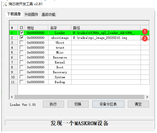
- Click to execute, you can see the content written on the right, it shows that the download is complete and the writing is successful, and the blue light on the development board is always on.


Mirror Flashing
- Download and install balenaEtcher-flashing mirror software.
- Open the balenaEtcher flashing software, insert the SSD into the NVME to USB3.0 card reader, and insert the card reader into the computer.
- Select the downloaded image file, click "Write" and wait for the writing to complete.
- Insert the M.2 NVME SSD into the M2 port on the bottom of the development board, plug in the power supply and it will start successfully.

Login
- Debian/Ubuntu default user account (non-root users)
Login name: rock
Login password: rock
Login via Serial Port
Equipment Preparation
- ROCK3 Model A motherboard
- FT232 USB to UART serial port module
- Power Adapter
- DuPont line
Serial Login
1.The default baud rate of ROCK3 Model A is 1500000 (1.5Mbps), check whether the FT232 USB to UART serial port module supports 1.5Mbps baud rate, we use here FT232 USB UART Board Type A.
2. USB to TTL connection ROCK3 Model A, first look at the ROCK 3A pin diagram, the pins we need to use are 6 (GND), 8 (TX), and 10 (RX).
 3. Wiring as shown:
 4. Download MobaXterm to log in to the software remotely, decompress it and use it.
5. Open MobaXterm remote login software, choose Session and select Serial.

6. After clicking OK, press Enter, and enter the login name and login password to log in.

Remote Login
Preparation
1.Connect one end of a network cable to the ROCK 3A and the other end to the router's LAN port.
Get IP address of ROCK3 Model A
1.Log in to the router for the IP address of ROCK3 Model A.
2.Use the ping command to find the cmd terminal on the computer, open the cmd terminal and enter
ping -4 rock-3a.local

-4 parameter is used to display the ping result in IPv4 IP format.
Login via MobaXterm
1.Download MobaXterm remote access software, decompress it and use it
2.Open MobaXterm remote access software, select Session and ssh
3.Enter the IP address 192.168.15.100 we queried earlier in the Remote host (fill in your actual IP), check Specify username, and fill in the ROCK3 Model A login name: rock.

4.After filling in, click ok, enter the ROCK3 Model A login password: rock (it is normal that the screen does not change when entering the password, click Enter to confirm)

Configuration
WIFI Connection
1. Switch to superuser mode
sudo su root
2. Turn on WIFI
nmcli r wifi
3. Scan WIFI
nmcli dev wifi
4. Connect to the WIFI network ("wifi_name" and "wifi_password" need to be replaced with the SSID and password of your actual WiFi.)
nmcli dev wifi connect wifi_name password "wifi_password"
5. If "successfully" is displayed, the wireless network is successfully connected, and the motherboard will automatically connect to the WiFi you specified next time it is powered on.
GPIO
Introduction
- GPIO: General-purpose input/output
- ROCK3 Model A Pinout
- Power pins: 5v, 3.3v, GND (Ground).
- Regular GPIO control pins: The high and low levels of these pins can be controlled by programming.
- Special GPIO communication pins: SPI communication, 12C communication, TxD/RxD serial communication.
- Power pins: 5v, 3.3v, GND (Ground).
- ROCK3 Model A has a 40-pin expansion header

GPIO Number Computing
- GPIO has 5 banks, GPIO0 to GPIO4, each bank has 32 pins, named as follows:
GPIO0_A0 ~ A7
GPIO0_B0 ~ B7
GPIO0_C0 ~ C7
GPIO0_D0 ~ D7
GPIO1_A0 ~ A7
....
GPIO1_D0 ~ D7
....
GPIO4_D0 ~ D7
For Linux 4.19 kernel, the number of GPIOs can be calculated as follows, taking GPIO4_D1 (PIN26 on 40PIN GPIO) as an example:
GPIO4_D1 = 4*32 + 3*8 + 1 = 153
(A=0, B=1, C=2, D=3)
Set GPIO4_D1 output:
sudo su root
cd /sys/class/gpio
echo 153 > export
cd gpio153
echo out > direction
echo 1 > value # high output
echo 0 > value # low output
IIC
Introduction
- I2C: integrated circuit bus;
- It is a serial communication bus, using a multi-master-slave architecture, developed by Philips in the 1980s to allow motherboards and embedded systems to connect low-speed peripherals. The correct pronunciation of I2C is "I-squared-C" ("I-squared-C") or 'I-squared-C'
I2C hardware connection
- The I2C bus is very simple in physical connection, consisting of SDA (serial data line) and SCL (serial clock line) and pull-up resistors.
- The communication principle is to generate the signals required by the I2C bus protocol for data transmission by controlling the high and low levels of SCL and SDA.
- When the bus is idle, SCL and SDA will be pulled high by the pull-up resistor and kept high.
Through its physical connection, we can know that the I2C protocol is a serial and synchronous communication protocol.
Feature
- Each device on the I2C bus will correspond to this unique I2C address, and some slave devices can change the I2C address through peripheral circuits.
- The master and slave devices use this address to determine which device to communicate with.
- Two-way data transmission is performed in units of bytes (8 bits) between the master device and the slave device on the I2C bus.
Protocol Detail

- The I2C protocol stipulates that the transmission of data on the bus must take a start signal as the start condition and an end signal as the stop condition of the transmission. The start and end signals are always generated by the master device (meaning that the slave device cannot initiate communication actively, all communications are initiated by the master device, the master can issue an inquiry command, and then wait for the communication from the slave device).

- When the bus is in an idle state, both SCL and SDA remain high. When SCL is high and SDA transitions from high to low, a start condition is generated; when the transfer is over, SCL is high and SDA is switched from A low-to-high transition indicates a stop condition.
- After the start condition is generated, the bus is in a busy state, the master-slave device of this data transfer occupies the bus, and other I2C devices cannot access the bus; after the stop condition is generated, the master-slave device of this data transfer will release the bus, the bus idle again
- Data transfers by bytes. The master device will transmit a data bit on the SDA line during the process of generating each clock pulse on the SCL line. When a byte is transmitted in the order of data bits from high to low, the slave device will pull low the SDA line. , and return an acknowledge bit to the master device, at which time it is considered that a byte has been truly transmitted. Of course, not all byte transfers must have an acknowledge bit. For example, when the slave device can no longer receive the data sent by the master device, the slave device will not return the acknowledge bit.
ROCK 3 Model A Interface
Enable I2C Interface
- ROCK3 Model A has a total of two i2c channels, namely I2C-3 (pin 3 and pin 5) and I2C-3 (pin 27 and pin 28). Taking I2C-3 as an example, the opening method is as follows:
Open the configuration file config.txt:
sudo nano /boot/uEnv.txt
add a line at the end of the file
overlays=rk3568-i2c3-m0

After the modification is completed, press and hold Ctrl+s on the keyboard to save, Ctrl+x to exit, and restart the device:
sudo reboot
After the restart is complete, we enter the following command in the terminal to check that the I2C-3 is successfully turned on:
ls /dev/i2c*

Hardware Connection
- This example uses 10-DOF IMU Sensor Module
| 10 DOF | ROCK3 Model A | Functioon |
| Board pinout number | ||
| VCC | 5V | power input |
| GND | GND | power grounf |
| SDA | 3 | I2C data input |
| SCL | 5 | I2C Clock Signal |

i2cdetect
|Query i2c devices:
sudo i2cdetect -y -r -a 3
- Parameters: -y is to execute directly ignoring interaction problems, -r is the SMBus read byte command, -a is all addresses, and 3 refers to i2c-3.
- Parameters: -y is to execute directly ignoring interaction problems, -r is the SMBus read byte command, -a is all addresses, and 3 refers to i2c-3.

SPI
Introduction
- SPI stands for Serial Peripheral Interface, which is a high-speed, full-duplex, synchronous communication bus.
- It works in a master-slave mode. In this mode, one master device usually corresponds to one or more slave devices. 4 lines are required for bidirectional data transmission, and 3 lines can be cut for unidirectional data transmission.
Hardware Connection
1. MOSI - Master output/slave input pin. This pin corresponds to the data sending pin of the master device and the data receiving pin of the slave device
2. MISO - Master input/slave output pin. This pin corresponds to the data receiving pin of the master device and the data sending pin of the slave device
3. SCLK - Synchronous clock, usually output by the master device.
4. CS – Select from device. Used to select slave devices. Its function is to allow the master device to communicate with a specific slave device, avoiding conflicts on the data lines.
Working Mode
The Linux kernel uses a combination of CPOL and CPHA to represent the four working modes of the current SPI:
CPOL=0,CPHA=0		SPI_MODE_0
CPOL=0,CPHA=1		SPI_MODE_1
CPOL=1,CPHA=0		SPI_MODE_2
CPOL=1,CPHA=1		SPI_MODE_3
- CPOL: indicates the state of the initial level of the clock signal, 0 is a low level, and 1 is a high level.
- CPHA: Indicates which clock edge is sampled, 0 is the first clock edge sampling, 1 is the second clock edge sampling.
- CPOL: indicates the state of the initial level of the clock signal, 0 is a low level, and 1 is a high level.
The waveforms of the four working modes of SPI are as follows:

Enable SPI Interface
- ROCK3 Model A has only one spi channel, which is spi-3 (pin 19, pin 21, pin 23, and pin 26). The way to turn it on is as follows:

1. Open config.txt:
sudo nano /boot/uEnv.txt
add the following demo at the end of the file
overlays=rk3568-spi3-m1-cs0-spidev
2. After the modification is completed, press and hold Ctrl+s on the keyboard to save, Ctrl+x to exit, and restart the device:
sudo reboot
3. After rebooting, we enter the following command in the terminal to check that the spi-3 is enabled:
ls /dev/spi*
Resource
Software
- Panasonic_SDFormatter
- Win32DiskImager
- DriverAssitant
- RKDevTool_Release
- rk356x_spl_loader_ddr1056-firmware
- MobaXterm
Drawing
Support
Technical Support
If you need technical support or have any feedback/review, please click the Submit Now button to submit a ticket, Our support team will check and reply to you within 1 to 2 working days. Please be patient as we make every effort to help you to resolve the issue.
Working Time: 9 AM - 6 PM GMT+8 (Monday to Friday)