
Platform Cable USB User Manual
Overview
Introduction
Platform Cable USB is suitable for XILINX CPLD/FPGA devices and allows programming and debugging of the device and its configuration chip through the USB interface of a computer.
- Platform Cable USB Function
- Adopt CY7C68013A+XC2C256 solution, fully compatible with the original Platform Cable USB.
- Support all Xilinx devices download, including FPGA / CPLD / ISP Configuration PROM devices.
- Support JTAG / Slave Serial / SPI download mode, which can be configured for all Xilinx devices.
- Support download interface voltage of target system: 5V / 3.3V / 2.5V / 1.8V / 1.5V.
- Xilinx ISE / iMPACT / ChipScope support.
- Optional target device download clock and auto-tuning support for XILINX software.
- Supported Software
- Xilinx ISE
- iMPACT
- ChipScope
- Supported Devices
- Support all Xilinx devices for download, including FPGA / CPLD / ISP Configuration PROM devices.
- New devices are constantly being added to ......
- Feature
- Adopt CY7C68013A+XC2C256 solution, fully compatible with the original Platform Cable USB
- Connect to PC
- Connect to computer via USB 2.0 interface
- Connect to Target Board
- Connect to the target board via JTAG, AS, or PS interface
- Platform Cable USB Status Indicator
- Red light is the power light.
- Green: USB is connected and Vref has a power supply into it (connected development board has power on).
Xilinx Platform Cable USB
Device Connection
- Software Development Platform
XILINX provides complete platform support for CPLD/FPGA development, mainly including:
- HDL development software: Xilinx ISE
- Simulation software: Modelsim-SE
- In addition to the third-party synthesis, simulation, and other tools to provide a software interface
- Hardware Development Platform
The hardware development platform is very simple, only a PC and a programming cable can be the online configuration of CPLD/FPGA or programming of serial configuration devices.
Connect to PC
Use a USB cable to connect the PC.
Connect to the Target Board
There are three interfaces for Platform Cable USB to connect to the target board.

- JTAG Adapter Interface

Software User Guide
Software Introduction
Introduction to common FPGA development software
| software_name | Introduction |
|---|---|
| Xilinx ISE | Xilinx ISE is XILINX's comprehensive PLD development software that supports schematic, VHDL, Verilog HDL, and other forms of design input, with its own synthesizer and emulator embedded to complete the complete PLD design flow from design input to hardware configuration. |
| SignalTap II | SignalTap II, known as SignalTap II Logic Analyzer, is a powerful and useful FPGA on-chip debug tool that captures and displays real-time signals and observes the interactions between hardware and software in a system design. |
| Modelsim-SE | Mentor's simulation software for XILINX CPLD/FPGA with features such as RTL-level and gate-level simulation. |
Download Demo to FPGA (No program loss during power failure)
XC3S250E is used as an example to configure the following chips. Platform Cable USB is used as an example to configure the downloader. You need to select the corresponding chip model and downloader during configuration.
After compiling, you can configure the information download, as shown below:
-
Click Xilinx ISE:

- Open the "LED4.xise" project under the verilog\LED\ directory in the 3S250E sample program (users can open any other project, here the LED program of this development board as an example), as shown in the following figure.
-
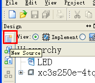
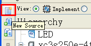
First select "1" and then double click "2", as shown below:

-
Double-click the Boundary Scan option in the pop-up field, as shown in the following figure:

-
First, left-click on the blank space, then right-click and select Cabel Setup, as shown in the figure below.

-
Select the appropriate download method, as shown below.

-
Go ahead and left-click on the blank space first, then right-click, as shown below.

-
Select the burn file, as shown in the following figure.

-
Choose No as shown below:

-
Operate as shown below:

-
Operate as shown below:

-
Right-click, and choose Program to download as shown below:
File:Xilinx ISE12.png
- Finished.


Download Program to FLASH (No program loss during power failure)
-
Click Xilinx ISE:
- Open the "LED4.xise" project under the verilog\LED\ directory in the 3S250E sample program (users can open any other project, here the LED program of this development board as an example), as shown in the following figure.
-
First select "1" and then double click "2", as shown below:
-
Double-click the BCreate PROM File option in the pop-up column, as shown in the following figure:

-
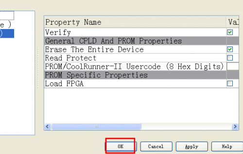
In the pop-up section, follow the steps as shown below, where step 5 saves the file to the corresponding project folder, as shown below.

-
Choose OK as shown below:

-
Open the specified file, as shown in the following image.

-
Choose No as shown below:

-
Choose OK as shown below:

-
First, left-click in the blank space, and then select Generate File, as shown in the figure below.

-
The download file was generated successfully, as shown in the image below.

-
Continue to click back to Boundary Scan, as shown in the figure below.

-
Right-click as shown below:

-
Choose to download the file as shown below:

-
Click Program to start download as shown below:

-
A pop-up selection of columns is shown below:
-
The download was successful, as shown in the following image:


New Project
The following configuration chip is XC3S250E for example, and the configuration downloader is Platform Cable USB for example, when configuring the corresponding chip model and downloader.
-
Click Xilinx ISE as shown below:

-
Input the project name and specify the storage path:

-
Set the project parameters such as chip, package, language and so on.

-
As shown below:

-
Name the new Verilog HDL file:
-
As shown below:

-
As shown below:

-
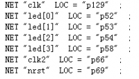
The code in Verilog HDL is as follows, and after writing the code, save it as follows:

-
Create pin configuration file:

-
As follows:
-
As follows:

-
Pin configuration file as shown below:
-
Click the following pattern to compile:

- Finished.


