
PN532 NFC HAT
| ||

Overview
Introduction
The PN532 NFC HAT is an NFC expansion board specifically designed for the Raspberry Pi, featuring the PN532 main controller and supporting I2C, SPI, and serial communication, enabling the Raspberry Pi to expand its NFC communication capabilities.
The PN532 is a highly integrated non-contact read/write chip that operates at 13.56MHz. It includes an 80C51 microcontroller core, integrated with 40Kbytes ROM and 1Kbytes RAM.
The PN532 completely integrates the concepts of modulation and demodulation into various non-contact communication methods and protocols at 13.56MHz, featuring user-friendly firmware suitable for different modes, as well as various host control interfaces.
Specifications
- Operating voltage 3.3V / 5V
- Factory communication baud rate: 115200 bps
- Supports ISO/IEC 14443A / MIFARE
- Supports ISO/IEC 14443B in reader mode
- The NFC module operates in the 13.56MHz band
Precautions
- This module can only be used to read and write NFC cards with known passwords or default passwords, and cannot be used to crack encrypted cards. For example, the default password for all blocks of the Mifare Classic card (except for block 0) is 0xFFFFFFFFFFFF, and it can only be read and written if the password is not modified.
- It normally cannot be used to duplicate a card unless the password for all blocks of the card has not been modified. If the correct password is not provided, the PN532 cannot read the corresponding block.
- It cannot be used to simulate a complete card. Because the ID of the card is generally 4 bytes, and due to the security policy of PN532, it will fix the first byte of the simulated card to 0x08. Please refer to http://www.nfc-tools.org/index.php?title=PN53x.
Unboxing Test
Users can quickly verify the functionality of the PN532 through the serial port using a computer without the need for a Raspberry Pi. A serial port to USB module (e.g. FT232 module) is required for verification.
- 1. Hardware connection
| PN532 NFC HAT | Serial port module |
|---|---|
| 3V3 | 3.3V |
| GND | GND |
| TX | RX |
| RX | TX |

- 2. Set I0 to L and I1 to L via the jumper cap
- 3. Connect the serial port module to the computer via USB cable
- 4. Open the serial port debugging assistant software and set the serial port
- Baud rate: 115200
- Data bits: 8
- Stop bits: 1
- Parity: None
- Flow control: None
- 5. Check "SendHEX" and "HEXShow"
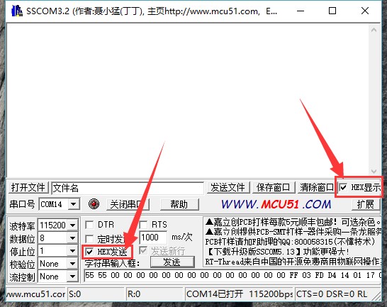

- 6. Select the corresponding serial port and open the serial port.
- 7. Send this frame to wake up the module
55 55 00 00 00 00 00 00 00 00 00 00 00 00 00 00 FF 03 FD D4 14 01 17 00
(See the HSU wake up condition section of the PN532 User Manual)
Module response frame:
00 00 FF 00 FF 00 00 00 FF 02 FE D5 15 16 00
- 8. Send this frame for detecting Mifare Classic card (the included blue drop-shaped card, hereinafter referred to as the "card")
00 00 FF 04 FC D4 4A 01 00 E1 00
Place the card close to the coil part of the module, and the module will respond:
00 00 FF 0C F4 D5 4B 01 01 00 04 08 04 XXXXXXXXXX 00
The XXXXXXXXX in this frame refers to a 4-byte card ID and a 1-byte checksum. (See the InListPassiveTarget section of the PN532 User Manual)
Demo Usage
The PN532 NFC HAT supports three interfaces: serial, I2C, and SPI. Users can use different interfaces as needed to enable communication between Raspberry Pi and module. After connecting the module to the Raspberry Pi, you need to select the working mode through the I0 and I1 jumpers. Additionally, use the DIP switch to connect the module's interface to the corresponding interface on the Raspberry Pi.
Please choose the interface according to your actual usage situation:
- UART: The UART on the Raspberry Pi is used for Shell communication by default. If your UART is used for communication with the Raspberry Pi and you want to use UART communication, you should connect the Raspberry Pi and the PN532 NFC HAT using a USB to serial module. Additionally, the serial port initialization in the demo should be changed to /dev/ttyUSB0 (fill in according to actual circumstances; you can check it via `ls /dev | grep ttyUSB`), rather than using the default value /dev/ttyS0 in the demo
- I2C: The Raspberry Pi does not support Clock Stretching for I2C interfaces, while the PN532's I2C operation may use Clock Stretching (the slave may actively pull down the I2C's SCL). This will cause the Raspberry Pi to be unable to control all I2C devices, including the PN532! If your I2C has mounted multiple devices, it is not advisable to use I2C and PN532 for communication.
- SPI: The SPI interface of the PN532 NFC HAT uses D4 (BCM) as the chip select. If other programs use this pin, it is not advisable to use the SPI interface for communication.
Raspberry Pi Demo
- Install wiringpi Library
git clone https://github.com/WiringPi/WiringPi.git
cd WiringPi
./build debian
mv debian-template/wiringpi-3.x.deb .
sudo apt install ./wiringpi-3.x.deb
Download the demo from demo, unzip it, and copy the raspberrypi folder to the /home/pi directory of the Raspberry Pi. You can first copy the demo to /boot/, then copy it to /home/pi
or run on the Raspberry Pi terminal:
sudo apt-get install p7zip-full python3-lgpio
wget https://files.waveshare.com/upload/6/67/pn532-nfc-hat-code.7z
7z x Pn532-nfc-hat-code.7z -r -o./Pn532-nfc-hat-code
sudo chmod 777 -R Pn532-nfc-hat-code/
- SPI Communication
1. Set I0 to L and l1 to H via the jumper cap
2. Connect RSTPDN to D20 using a jumper cap
3. Set the DIP switch to
| SCK | MISO | MOSI | NSS | SCL | SDA | RX | TX |
| ON | ON | ON | ON | OFF | OFF | OFF | OFF |

4. Insert the PN532 NFC HAT into the 40PIN GPIO on the Raspberry Pi
| PN532 NFC HAT | Raspberry Pi (BCM) |
|---|---|
| SCK | SCK |
| MISO | MISO |
| MOSI | MOSI |
| NSS | P4 |
5. Enable SPI interface
Open the Raspberry Pi terminal and run sudo raspi-config to enter the configuration interface
Select Interfacing Options -> SPI -> Yes
6. Execute the demo (taking example_get_uid.py and rpi_get_uid.c as examples)
Open the terminal and enter the demo directory:
cd ~/raspberrypi/
1) python demo:
Enter the Python demo directory:
cd ~/raspberrypi/python/
Modify the example_get_uid.py file, change the statements related to initializing the pn532 object to:
pn532 = PN532_SPI(debug=False, reset=20, cs=4)
#pn532 = PN532_I2C(debug=False, reset=20, req=16)
#pn532 = PN532_UART(debug=False, reset=20)
After the modification, save and run the demo
sudo python3 example_get_uid.py
2) C demo: Since different motherboards may have different serial port numbers, if you need to modify the port number, you can enter the corresponding directory:
cd ~/raspberrypi/c/
Modify the pn532_rpi.c file, find the ttyS0 setting, and modify it according to the actual situation
Go to the C demo directory: cd ~/raspberrypi/c/example/
Modify the rpi_get_uid.c file, change the statements related to initializing the pn532 to:
PN532_SPI_Init(&pn532);
//PN532_I2C_Init(&pn532);
//PN532_UART_Init(&pn532);
Save the file, and recompile: sudo make
Run the demo:
./rpi_get_uid.exe
7. Expected result: By placing the card close to the coil part of the module, the UID information of the card can be read
- UART Communication
1. Set I0 to L and l1 to L via the jumper cap
2. Connect RSTPDN to D20 using a jumper cap
3. Set the DIP switch to
| SCK | MISO | MOSI | NSS | SCL | SDA | RX | TX |
| OFF | OFF | OFF | OFF | OFF | OFF | ON | ON |

4. Insert the PN532 NFC HAT into the 40PIN GPIO on the Raspberry Pi
| PN532 NFC HAT | Raspberry Pi |
|---|---|
| 3V3 | 3.3V |
| GND | GND |
| TXD | RXD |
| RXD | TXD |
5. Start the Raspberry Pi serial port. By default, the serial port on the Raspberry Pi is used for logging into the Shell terminal. If you need to use the serial port to communicate with external devices, you need to manually enable the hardware serial port
Open the Raspberry Pi terminal and input sudo raspi-config to enter the configuration interface
Select Interfacing Options-> Serial -> No -> Yes
Note: After enabling the hardware serial port here, a restart may be required. A normal restart is sufficient
6. Run the demo (taking example_get_uid.py and rpi_get_uid.c as examples)
Open the terminal and enter the demo directory:
cd ~/raspberrypi/
1) python demo:
Enter the Python demo directory: cd ~/raspberrypi/python/
Modify the example_get_uid.py file, change the statements related to initializing the pn532 object to:
#pn532 = PN532_SPI(debug=False, reset=20, cs=4)
#pn532 = PN532_I2C(debug=False, reset=20, req=16)
pn532 = PN532_UART(debug=False, reset=20)
After the modification, save and run the demo
python3 example_get_uid.py
2) C demo:
Go to the C demo directory: cd ~/raspberrypi/c/example/
Modify the rpi_get_uid.c file, change the statements related to initializing the pn532 to:
//PN532_SPI_Init(&pn532);
//PN532_I2C_Init(&pn532);
PN532_UART_Init(&pn532);
Save the file, and recompile: sudo make
Run the demo:
./rpi_get_uid.exe
7. Expected result: By placing the card close to the coil part of the module, the UID information of the card can be read
- If the demo fails to run, you can use the following demo to test the serial port
cd ~/raspberrypi/python/
python3 example_uart_hex.py
Enter the original data in hexadecimal format and press Enter to send. The terminal will display the sent data and the received details. For example, send the following data to wake up the module:
55 55 00 00 00 00 00 00 00 00 00 00 00 00 00 00 FF 03 FD D4 14 01 17 00
The terminal displays the response data of the module:
00 00 FF 00 FF 00 00 00 FF 02 FE D5 15 16 00
- I2C Communication
1. Use the jumper cap to set I0 to H and l1 to L
2. Connect RSTPDN to D20 via a jumper cap, connect INT0 to D16 (to avoid Clock Stretching)
3. Set the DIP switch to
| SCK | MISO | MOSI | NSS | SCL | SDA | RX | TX |
| OFF | OFF | OFF | OFF | ON | ON | OFF | OFF |

4. Insert the PN532 NFC HAT into the 40PIN GPIO on the Raspberry Pi
| PN532 NFC HAT | Raspberry Pi |
|---|---|
| SCL | SCL |
| SDA | SDA |
5. Start the Raspberry Pi I2C interface.
Open the Raspberry Pi terminal and input sudo raspi-config to enter the configuration interface
Select Interfacing Options -> I2C -> Yes
6. Run the demo (taking example_get_uid.py and rpi_get_uid.c as examples)
Open the terminal and enter the demo directory:
cd ~/raspberrypi/
1) python demo:
Enter the Python demo directory: cd ~/raspberrypi/python/
Modify the example_get_uid.py file, change the statements related to initializing the pn532 object to:
#pn532 = PN532_SPI(debug=False, reset=20, cs=4)
pn532 = PN532_I2C(debug=False, reset=20, req=16)
#pn532 = PN532_UART(debug=False, reset=20)
After the modification, save and run the demo
python3 example_get_uid.py
2) C demo:
Go to the C demo directory: cd ~/raspberrypi/c/example/
Modify the rpi_get_uid.c file, change the statements related to initializing the pn532 to:
//PN532_SPI_Init(&pn532);
PN532_I2C_Init(&pn532);
//PN532_UART_Init(&pn532);
Save the file, and recompile: sudo make
Run the demo:
./rpi_get_uid.exe
7. Expected result: By placing the card close to the coil part of the module, the UID information of the card can be read
Arduino Demo
1. The computer needs to install Arduino IDE.
2. Create a new folder under the Arduino project folder (default is C:\Program Files (x86)\Arduino\libraries, which can be specified via Arduino IDE's File → Preferences → Sketchbook location), and rename it pn532.
3. Copy the four files pn532.c, pn532.h, pn532_uno.cpp, and pn532_uno.h to the Arduino\libraries\pn532 folder.
4. The demo is located in the examples\arduino directory.
5. The following is an example of an Arduino UNO development board
- SPI Communication
1. Set I0 to L and l1 to H via the jumper cap
2. Set the DIP switch to:
| SCK | MISO | MOSI | NSS | SCL | SDA | RX | TX |
| ON | ON | ON | ON | OFF | OFF | OFF | OFF |
3. Connect the PN532 NFC HAT to Arduino:
| PN532 NFC HAT | Arduino UNO |
|---|---|
| SCK | D13 |
| MISO | D12 |
| MOSI | D11 |
| NSS | D4 |

4. Execute the demo (taking examples\arduino\uno_get_uid\ uno_get_uid.ino as examples):
Double-click to open the uno_get_uid.ino file, change the statements related to initializing the pn532 to:
PN532_SPI_Init(&pn532);
//PN532_I2C_Init(&pn532);
Compile and upload demo to the Arduino UNO
Open the serial monitor and press the Reset button on the Arduino UNO
5. Expected results: Place the card close to the coil part of the module to read the UID of the card
- I2C Communication
1. Set I0 to L and l1 to H via the jumper cap
2. Set the DIP switch to
| SCK | MISO | MOSI | NSS | SCL | SDA | RX | TX |
| OFF | OFF | OFF | OFF | ON | ON | OFF | OFF |
3. Connect the PN532 NFC HAT to Arduino UNO:
| PN532 NFC HAT | Arduino UNO |
|---|---|
| SCL | A5 |
| SDA | A4 |

4. Execute the demo (taking examples\arduino\uno_get_uid\ uno_get_uid.ino as examples):
Double-click to open the uno_get_uid.ino file, change the statements related to initializing the pn532 to:
//PN532_SPI_Init(&pn532);
PN532_I2C_Init(&pn532);
Compile and upload demo to the Arduino UNO
Open the serial monitor and press the Reset button on the Arduino UNO
5. Expected results: Place the card close to the coil part of the module to read the UID of the card
STM32 Demo
The development board used in the demo is the Open103C, and the main control chip is the STM32F103CBT6. For STM32 demo, we only provide SPI communication method. If other communication methods are needed, they need to be added manually
- Download Project
1. Open the project file (demo\MDK-ARM\pn532_stm32.uvprojx) using keil and click Rebuild to compile the project.
2. Select the downloader: Options for Target -> Debug tab-> Use, which is ST-Link Debugger by default.
3. Select the download interface: Options for Target -> Debug tab -> Settings -> Debug tab -> Port, JTAG by default.
4. Connect the development board to the computer via the downloader.
5. Click Download to download the project.
- Hardware Connection
1. Set I0 to L and I1 to H via the jumper cap
2. Set the DIP switch to
| SCK | MISO | MOSI | NSS | SCL | SDA | RX | TX |
| ON | ON | ON | ON | OFF | OFF | OFF | OFF |
3. Connect the PN532 NFC HAT to the STM32 development board
| PN532 NFC HAT | STM32F103CBT6 |
|---|---|
| SCK | PA5 |
| MISO | PA6 |
| MOSI | PA7 |
| NSS | PA4 |
4. Connect the UART1 interface (PA9->RX, PA10->TX) of the STM32 development board to the computer via a USB serial cable or serial module
5. Open the serial monitor and press the Reset button on the STM32 development board
6. Expected results: Place the card close to the coil part of the module to read the UID of the card
Demo Description
The above demonstration is an example of obtaining the ID of a Mifare Classic card (example_get_uid.py / rpi_get_uid.exe / uno_get_uid.ino / stm32_get_uid), and the other example programs will be illustrated below.
Note:
Before using these programs, please set the I0 / I1 jumper and DIP switch of the PN532 NFC HAT according to the actual situation. The DIP switch cannot be set to ON at the same time, otherwise the correct data cannot be received. For simplicity, 0 indicates the DIP switch is set to OFF, and 1 indicates the DIP switch is set to ON.
- When using the UART interface, [I1.. I0] jumper should be set to LL and the DIP switch should be set to 00000011
- When using the I2C interface, [I1.. I0] jumper should be set to LH and the DIP switch should be set to 00001100
- When using the SPI interface, [I1.. I0] jumper should be set to HL and the DIP switch should be set to 11110000
Read Mifare Classic Card
| Demo | Development board |
| example_dump_mifare.py | Raspberry Pi |
| rpi_dump_mifare.c | Raspberry Pi |
| uno_dump_mifare.ino | Arduino UNO |
| stm32_dump_mifare/MDK-ARM/pn532_stm32.uvprojx | STM32F103CBT6 |
Expected result: When the Mifare Classic card is placed close to the PN532 NFC HAT, the contents of the card will be printed out
0 : 37 F9 20 69 87 08 04 00 62 63 64 65 66 67 68 69
1 : 00 00 00 00 00 00 00 00 00 00 00 00 00 00 00 00
2 : 00 00 00 00 00 00 00 00 00 00 00 00 00 00 00 00
3 : 00 00 00 00 00 00 FF 07 80 69 FF FF FF FF FF FF
4 : 00 00 00 00 00 00 00 00 00 00 00 00 00 00 00 00
5 : 00 00 00 00 00 00 00 00 00 00 00 00 00 00 00 00
6 : 00 00 00 00 00 00 00 00 00 00 00 00 00 00 00 00
7 : 00 00 00 00 00 00 FF 07 80 69 FF FF FF FF FF FF
8 : 00 00 00 00 00 00 00 00 00 00 00 00 00 00 00 00
9 : 00 00 00 00 00 00 00 00 00 00 00 00 00 00 00 00
10 : 00 00 00 00 00 00 00 00 00 00 00 00 00 00 00 00
11 : 00 00 00 00 00 00 FF 07 80 69 FF FF FF FF FF FF
… …
63 : 00 00 00 00 00 00 FF 07 80 69 FF FF FF FF FF FF
Instructions:
- The content displayed on each line is the content of the corresponding block
- The first 4 bytes of block 0 are the UID of a Mifare Classic card, and the 5th byte is the parity bit, which is the XOR result of the first 4 bytes
- The 0th block (UID) of a regular card cannot be modified
- Every 4 blocks belong to the same sector and share the same password, for example, blocks 4N~4N+3 belong to the same sector.
- The 4N+3 block is a password block, and accordingly, if you want to read the contents of the 4N~4N+2 blocks, you must use the password recorded in the 4N+3 block
- A card with a capacity of 1K, consisting of 64 blocks in total
For example, when reading the 6th block, the password for the corresponding sector must be used, which is the password for the first 6 bytes (KEY A) or the last 6 bytes (KEY B) of the 7th block
7 : 00 00 00 00 00 00 FF 07 80 69 FF FF FF FF FF FF
The first 6 bytes are KEY A, which defaults to FF FF FF, but its read result is always 00 00 00 00 00 00 00. The last 6 bytes are KEY B, stored in plaintext, and the default KEY A and KEY B for Mifare Classic cards are both FF FF FF FF FF FF.
The middle 4 bytes are access control bits (Access Bits). The default value is FF 07 80 69, which is used for sector write access permission control. If the user writes an inappropriate value, it will cause the card to be locked.

For example, if byte6 is written as 0xFF, then the high 4 bits of byte7 must be 0b0000, and the low 4 bits of byte8 must be 0b0000. Refer to the "Access conditions for data blocks" section in MF1S50YYX_V1.pdf for details.
The card that comes with the product is a magic card that can be unlocked through a reserved backdoor, but users should know that if they use a regular Mifare card, once the access control bit is written incorrectly, it will not be repaired. So pay special attention when writing cards.
Read/Write Mifare Classic Card
| Demo | Development board |
| example_rw_mifare.py | Raspberry Pi |
| rpi_rw_mifare.c | Raspberry Pi |
| uno_rw_mifare.ino | Arduino UNO |
| stm32_rw_mifare/MDK-ARM/pn532_stm32.uvprojx | STM32F103CBT6 |
Expected result: If the Mifare Classic card is placed close to PN532 NFC HAT, the content of block 6 will be rewritten to 00 01 02 03 04 05 06 07 08 09 0A 0B 0C 0D 0E 0F.
Instructions:
- Before writing the content of block 6, you need to ensure that the password corresponding to block 6 is 0xFF FF FF FF FF. This password is the first 6 bytes of block 7 (the read result is always 0x00 00 00 00 00 00 00).
- If the user modifies the demo, trying to write to the N+3 block, they should be particularly careful. Because the content of this part is the password of N ~ N+2 blocks. One should remember the written password, if the password is forgotten, all blocks in the sector will be unable to read or write.
Read NTAG2XX Card
| Demo | Development board |
| example_dump_ntag2.py | Raspberry Pi |
| rpi_dump_ntag2.c | Raspberry Pi |
| uno_dump_ntag2.ino | Arduino UNO |
| stm32_dump_ntag2/MDK-ARM/pn532_stm32.uvprojx | STM32F103CBT6 |
Expected result: Place the Ntag215 card close to the PN532 NFC HAT, and the contents of the card will be printed out
0: 04 85 32 3b
1: 92 a8 64 80
2: de 48 00 00
3: e1 10 3e 00
4: 03 00 fe 00
5: 00 00 00 00
6: 00 00 00 00
7: 00 00 00 00
… …
134: 00 00 00 00
Instructions:
- Ntag215 cards need to be purchased by the user.
- According to convention, the page of Ntag215 is equivalent to the block of Mifare, with one line representing one page.
- The first 3 bytes of page 0 are UID0-UID2, the 4th byte is the checksum, which is the XOR result of the first 3 bytes and 0x88 (Cascade Tag, defined by ISO/IEC 14443-3 Type A).
- The 4 bytes on page 1 are UID3-UID6.
- The first byte on page 2 is the parity bit, which is the XOR result of UID3-UID6
Read/Write NTAG2XX Card
| Demo | Development board |
| example_rw_ntag2.py | Raspberry Pi |
| rpi_rw_ntag2.c | Raspberry Pi |
| uno_rw_ntag2.ino | Arduino UNO |
| stm32_rw_ntag2/MDK-ARM/pn532_stm32.uvprojx | STM32F103CBT6 |
Expected result: Place the NTAG215 card close to the PN532 NFC HAT, the content of block 6 will be rewritten to 00 01 02 03.
Instructions:
- The last two bytes on page 2 are used to mark and lock the corresponding pages from 03h to 0Fh as read-only, and this operation is irreversible. Attention should be paid to this situation when using it. Refer to the Static lock bytes (NTAG21x) section of NTAG213/215/216.

- To lock the data after the 10th page, write the corresponding address to the first 3 bytes of page 28h (NTAG213), page 82h (NTAG215), or page E2h (NTAG216), and the 4th byte will always read as 0xBD. Refer to the Dynamic Lock Bytes section of NTAG213/215/216.

- For details on the functions of the Ntag2xx card, please refer to the NTAG213/215/216 manual.
Set GPIO level of PN532
| Demo | Development board |
| example_write_gpio.py | Raspberry Pi |
| rpi_write_gpio.c | Raspberry Pi |
| uno_write_gpio.ino | Arduino UNO |
| stm32_write_gpio/MDK-ARM/pn532_stm32.uvprojx | STM32F103CBT6 |
Expected result: Print the GPIO level of the PN532
Pin P30: 1
Pin P31: 0
Pin P32: 1
Pin P33: 0
Pin P34: 1
Pin P35: 0
Pin P71: 0
Pin P72: 1
Pin I0: 1
Pin I1: 0
Instructions:
The program attempts to set the pin levels: P30 -> high, P31 -> low, P33 -> low, P35 -> low, P71 -> low, P72 -> high
Note:
- P32 is int0, once a low level is written, it will cause the module to reset.
- P34 is SIC_CLK, the read result is high level.
- P71 is MISO, in SPI mode, the read result is high level.
- P72 is SCK, in SPI mode, the read result is high level.
- When the module is powered on, the PN532 will set the communication interface according to the level of I0/I1. After that, the jumper cap can be removed and it is used as a regular GPIO.
The P30 – P35 levels of the PN532 will return to a high level after a hardware reset (RSTPDN is low for 2ms then high).
Read GPIO Level of PN532
| Demo | Development board |
| example_read_gpio.py | Raspberry Pi |
| rpi_read_gpio.c | Raspberry Pi |
| uno_read_gpio.ino | Arduino UNO |
| stm32_read_gpio/MDK-ARM/pn532_stm32.uvprojx | STM32F103CBT6 |
Expected result: Print the GPIO level of the PN532
Port P3: 0x3f
Port P7: 0x07
Port I: 0x07
Pin P30: 1
Pin P31: 1
Pin P32: 1
Pin P33: 1
Pin P34: 1
Pin P35: 1
Pin I0: 1
Pin I1: 0
Instructions:
- The P30 – P35 levels of the PN532 will return to a high level after a hardware reset (RSTPDN is low for 2ms then high).
Resources
Documents
- Schematic
- PN532UM User Manual
- MF1S50YYX_V1 Datasheet
- NTAG213_215_216 Datasheet
- PN532DS Datasheet
- NFC-tools Reference Manual
- Pn532_nfc_hat_3D
Demo
Related Tutorial
FAQ
The NFC card can be formatted using the following program:
wget https://files.waveshare.com/upload/8/85/Pn532test.zip
unzip Pn532test.zip
cd pn532test/
sudo sh install.sh
sudo python3 test.py
- 1) The PN532 NFC HAT can be set to simulated card mode, allowing sensor data to be written to the module storage area via a main controller such as the Raspberry Pi, ESP32, or STM32
- 2) The phone's NFC can directly read simulated card data, but the first byte of the simulated card number is fixed to 0x08
- 3) This module only supports reading and writing NFC cards that are unencrypted or have known passwords. It cannot crack encrypted cards or fully copy the original card
Support
Technical Support
If you need technical support or have any feedback/review, please click the Submit Now button to submit a ticket, Our support team will check and reply to you within 1 to 2 working days. Please be patient as we make every effort to help you to resolve the issue.
Working Time: 9 AM - 6 PM GMT+8 (Monday to Friday)