
LCD CAPE (7inch)
| ||
| ||


Introduction
BB Black Expansion CAPE, Supports 7inch LCD
| More |
Getting Ready
Writing the TF Card System Image
Follow the steps below to write the Angstrom into TF card:
1) Extract the system image
Extract the system image file .img.7z by using archiver software like 7z920.exe.
Note: please download the image file from:
LCD CPAE(4.3inch) image for testing
LCD CPAE(7inch) image for testing
MISC CAPE and RS485/CAN CAPE image for testing
2) Format the TF card
Use HPUSBDisk.exe to format the TF card.
Choose the Device as your TF card, File system as FAT32. Then click Start.
Note: the TF card capacity should be 4GB or above!
- Use HPUSBDisk.exe to format the TF card

3) Writing the system image
Launch Win32DiskImager.exe, select the extracted system image. Then click write.
- Use Win32DiskImager.exe to write the system image

Install USB to UART driver
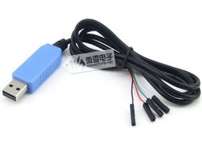
1) Connect the LCD CAPE with USB TO UART interface to the PC through a USB cable.
Note: You need to install the corresponding driver. Please refer to the respective manuals of your USB TO UART module.
Interface definition:
- Red: VCC
- Black: GND
- Green: TXD(connect to RXD)
- White: RXD(connect to TXD)
- USB to UART Cable

2) Open PL2303_Prolific_DriverInstaller_v1.8.0.exe and install the driver.
3) Launch putty.exe, configure as follows, then click Open.
- PuTTY Settings


Note:
- Serial line: check the PC "Device Manager" to confirm which COM port should be selected.
- Speed: 115200
- Connection type: Serial
Enter Bash Shell
1) Insert the TF card into the BeagleBone Black onboard slot, keep pressing down the BOOT button, power up the board, then release the BOOT button.
2) When the system startups, input "root" to enter Bash Shell environment, now the shell commands are available to use. All the commands follows are executed here.
- Enter Bash Shell
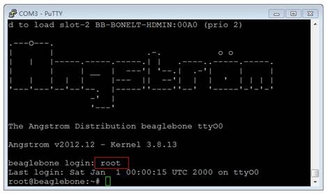

Note: please make sure that you are using the TF card image that we provide, and the system should boot from TF card (keep pressing down BOOT button, then power up), otherwise, the testing will fail.
API Source Code
The API source code can be found on /home/xuser/waveshare_demo/API.
LCD CAPE
LCD Display Overview

- BB_BLACK connector : for connecting BB Black
- 4.3inch LCD interface : for connecting 4.3inch resistive touchscreen LCD
- DEBUG interface : BB Black debug interface, for connecting serial modules
- BOOT selection button: Boot from TF card

- BB_BLACK connector : for connecting BB Black
- 7inch LCD interface : for connecting 7inch resistive touchscreen LCD
- DEBUG interface : BB Black debug interface, for connecting serial modules
- BOOT selection button : Boot from TF card
LCD Display
1) Connect to a LCD
Note: There are two models of LCD CAPE, LCD CAPE (4.3inch) and LCD CAPE (7inch), each one corresponds our 4.3inch or 7inch resistive touch screen respectively. Some batches of LCD CAPE provide both interfaces. If the CAPE connected to the LCD by a wrong interface, it may damage the LCD and the main board.
- When using 4.3inch LCD
Download LCD CPAE(4.3inch) image for testing.
Connect BB Black to the 4.3inch LCD.
- Connect to the 4.3inch LCD


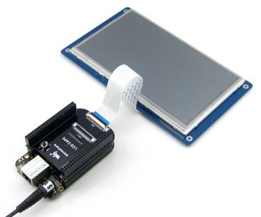
- When using 7inch LCD
Download LCD CPAE(7inch) image for testing.
Connect BB Black to the 7inch LCD.
- Connect to the 7inch LCD

2) The touchscreen should be calibrated when the display mode has been changed:
root@beaglebone:~# rm -rf /etc/pointercal*
root@beaglebone:~# ts_calibrate
root@beaglebone:~# sync
Reboot the system. Note: if the calibration failed, reboot and retry again.
MISC CAPE
MISC CAPE Overview

- BB_BLACK connector : for connecting BB Black
- DEBUG interface : BB Black debug interface, for connecting serial modules
- ONE-WIRE interface: easily connects to ONE-WIRE devices (TO-92 package), such as temperature sensor (DS18B20), electronic registration number (DS2401), etc.
- BOOT selection button : Boot from TF card
- User button : 4 buttons
- Buzzer
- Power indicator
- User LED : 4 LEDs
- Potentiometer : AD adjustable potentiometer
- 32.768KHz crystal : for RTC
- PCF8563 : RTC
- RTC battery holder : for 3.3V battery
- RTC power selection jumper
- RTC I2C selection jumper: select I2C1 OR I2C2
LED
Short the LED jumper, enter:
root@beaglebone:~# test_led
The 4 LEDs will light up one by one, press Ctrl+C to exit.
Buzzer
1) Short the buzzer jumper, enter:
root@beaglebone:~# ls /sys/devices/ocp.3/
You'll find the “pwm_ehrpwm1b.14” as shown:
- Find the “pwm_ehrpwm1b.14”


2) Because the pwm_ehrpwm1b.14's extension is .14. It is needed to add parameter 14 when buzzer tested.
root@beaglebone:~# test_pwm 14
The buzzer will make sounds in different frequency.
DS18B20
1) Insert the DS18B20 into the 1-WIRE socket, short the 1-WIRE jumper, enter:
root@beaglebone:~#ls /sys/bus/w1/devices/
You will find the "28-00000 57c5948" (the last 7 characters are unique for each DS18B20, it depends)
2) Execute:
root@beaglebone:~#test_ds18b20 57c5948
The terminal will print the current temperature.
Buttons
1) Execute
root@beaglebone:~# test_key event2
Note: Device file "event2" is based on user‘s device, Not necessarily "event2". you can execute the following command to view:
root@beaglebone:~# ls /dev/input
- Check event device


2) Press any of the onboard buttons, the terminal will show which one has been pressed, press Ctrl+C to exit.
Note: if the LCD screen was connected while testing joystick/buttons, the LCD screen seems that it was touched at the same time, it's normal.
RTC
Confirm that the module is powered by onboard battery.
1) Show system date time:
root@beaglebone:~# date
2) Set system date time:
root@beaglebone:~# date 020809302014.23
3) Set the hardware clock of RTC module:
root@beaglebone:~# hwclock –w –f /dev/rtc1
4) Show the hardware clock of RTC module:
root@beaglebone:~# hwclock –r –f /dev/rtc1
5) Synchronize the hardware clock to system date time:
root@beaglebone:~# hwclock –s –f /dev/rtc1
- Synchronize the hardware clock to system date time


6) Power off and reboot, read the hardware clock of RTC module and synchronize to system date time:
root@beaglebone:~# hwclock –r –f /dev/rtc1
root@beaglebone:~# hwclock –s –f /dev/rtc1
root@beaglebone:~# date
- Synchronize to system date time


Now the date time of software and hardware are synchronous.
RS485 CAN CAPE
CAN
Two BeagleBone Black and two RS485/CAN CAPEs are required for this testing. Set jumper to enable UART1(RXD1, TXD1). Connect two CAN Board to CAN1 interface separately, connect the CANH, CANL of one module to the CANH, CANL of another module via jumper wires.
1) Configure the baud rate:
root@beaglebone:~#canconfig can0 bitrate 115200 ctrlmode triple-sampling on
2) Enable the CAN device:
root@beaglebone:~# canconfig can0 start
The two CAN devices act as receiver and sender separately. The receiver gets ready to receive data first, and then the sender starts sending data.
3) Receiver:
root@beaglebone:~# candump can0
As shown in the picture:
- CAN receiver status


4) Sender:
root@beaglebone:~# cansend can0 -i 0x11 0x12 0x13 0x14
As shown in the picture:
- CAN wender status


5) Stop the devices:
root@beaglebone:~# canconfig can0 stop
RS485
Two BeagleBone Black and two RS485/CAN CAPEs are required for this testing. Set jumper to enable UART2(RXD2, TXD2). Connect two RS485 Boards to UART2 interface separately. Connect the A, B of one module to the A, B of another module via jumper wires.
The two RS485 devices act as receiver and sender separately.
1) The receiver gets ready to receive data first, and then the sender starts sending data. Execute:
root@beaglebone:~# test_485 –d /dev/ttyO2 –b 115200
2) Receiver:
Select "2", it will keep receiving data until you select "3".
As shown in the picture:
- RS485 receiver status


3) Sender:
Select "1", and then enter the message, say, "abc", it loops sending the message until you select "3".
As shown in the picture:
- RS485 sender status


4) Press Ctrl+C to exit.
Other Expansion Module
USB Camera
1) Connect the USB Camera to the BeagleBone Black USB Host connector.
2) Check the assigned IP:
root@beaglebone:~# ifconfig eth0
- Check the assigned IP


As shown in the picture, the IP is 192.168.1.143. Note this IP(it depends).
3) Start up the video stream server:
root@beaglebone:~# cd/home/xuser/waveshare_demo/API/camera_test/mjpg-streamer
root@beaglebone:~# ./ start.sh
- Start up the video stream server


4) Open browser on the PC in the same local network, visit the following address to view the video (default port number is 8080):
http://192.168.1.143:8080/javascript.html
(It depends on the IP you have noted)
- Visit video stream server


5) Press Ctrl+C to exit.
USB WIFI
1) Config the wireless network:
a) Power off, connect the USB WIFI module to the BeagleBone Black USB Host connector, and power up again.
b) Check the USB status:
root@beaglebone:~# lsusb
- Check the USB status:


c) Check the network status:
root@beaglebone:~# ifconfig
- Check the network status


d) Shut down the Ethernet NIC, and start up the WIFI NIC:
root@beaglebone:~# ifconfig eth0 down
root@beaglebone:~# ifconfig wlan0 up
e)Check the WIFI status:
root@beaglebone:~# ifconfig
- Check the WIFI status:


There's no AP connected, therefore, the wlan0 RX TX packets are both 0.
f) Config the wlan0 IP:
root@beaglebone:~# ifconfig wlan0 192.168.2.107
g) Config the gateway:
root@beaglebone:~# route add default gw 192.168.2.1
h) Config the DNS:
root@beaglebone:~# vi /etc/resolv.conf
Edit
nameserver 127.0.0.1
As:
nameserver 8.8.8.8
- Configure the DNS.


Save and exit.
i) Scan wireless router:
root@beaglebone:~# iwlist wlan0 scan
- Scan wireless router


2) Connect to the router:
a) Config the key file /etc/wpa_supplicant.conf:
root@beaglebone:~# vi /etc/wpa_supplicant.conf
Edit:
network={

    key_mgmt=NONE

}
As:
network={

    ssid="waveshare"

    psk="12345678"

}
Save and exit.
b) Connect manually:
root@beaglebone:~# wpa_supplicant -B -i wlan0 -c /etc/wpa_supplicant.conf
c) Test the connection:
root@beaglebone:~# ping www.baidu.com
- Test WIFI connection:


Resources
Documentations
Tools
PL2303_Prolific_DriverInstaller_v1.8.0
Win32DiskImager
7z920.exe
HPUSBDisk
putty
Cross-compilation toolchain
arm-2010.09-50-arm-none-linux-gnueabi-i686-pc-linux-gnu.tar
Source Code
driver
dts
tslib
wifi
mjpg-streamer
Kernel
- bb-black-Angstrom-kernel-3.8.13.tar.bz2
- bb-black-Angstrom-kernel-3.8.13-hdmi-waveshare.tar.bz2
- bb-black-Angstrom-kernel-3.8.13-lcd-waveshare.tar.bz2
- bb-black-Debian-kernel-3.8.13.tar.bz2
- bb-black-Debian-kernel-3.8.13-hdmi-waveshare.tar.bz2
- bb-black-Debian-kernel-3.8.13-lcd-waveshare.tar.bz2
- readme.txt
Kernel_config
Technical Support
If you need technical support or have any feedback/review, please click the Submit Now button to submit a ticket, Our support team will check and reply to you within 1 to 2 working days. Please be patient as we make every effort to help you to resolve the issue.
Working Time: 9 AM - 6 PM GMT+8 (Monday to Friday)