
Template: MLX90640 Thermal Camera manul
Interface
- Vcc: Connect to 3,3V (MCU)
- GND: Connect to GND (MCU)
- SDA: Connect to SDA pin of I2C interface (MCU)
- SCL: Connect to SCL pin of I2C interface (MCU)
I2C
This camera use the I2C interface supports High-speed mode. The default I2C address is 0x33.

Pixel position
MLX90640 consists of 768 IR sensors (also called pixels). Each pixel is identified with its row and column position as Pix(i, j) where i is its row number (from 1 to 24) and j is its column number (from 1 to 32)

It is normal that the sensor may has less than four bad pixels. Every bad pixel is marked in EEPROM table. So the module you get may have bad pixels, it is normal and not covered by warranty. If the module you get has bad pixels, you can use the average value of the neighboring pixels.
Address map

RAM

EEPROM
The EEPROM is used to store the calibration constants and the configuration parameters of the device

Refresh rate
This module support 8 kinds of refresh rate, up to 64Hz. The refresh rate is configured by registers 1-0x800D

The refresh rate is defined by Bit 7, Bit 8 and Bit 9 of control registers 1-0x800D.
Reading patterns
Chess pattern mode (factory default)

TV interleave mode

The array frame is divided into two subpages and depending on bit 12 in “Control register 1” (0x800D). As a standard the MLX90640 is calibrated in Chess pattern mode, this results in better-fixed pattern noise behavior of the sensor when in chess pattern mode. For best results, we advise to use chess pattern mode.
Measure principle
The FOV of this module is determined by 50% radiation signal which is received by the thermopile, it is also influenced by the main axis of the sensor. The temperature measured is the weighted average of the detected object's temperature in FOV. To improve the accuracy, you should make sure that the detected object is in the FOV totally.

Examples
Raspberry Pi
- Hardware connection


| Raspberry Pi | MLX90640 Thermal Camera |
|---|---|
| 5V | 5V |
| GND | GND |
| SDA(BCM2) | SDA |
| SCL(BCM3) | SCL |
- Download the demo codes and use it.
cd ~
wget http://www.waveshare.net/w/upload/5/56/MLX90640_Thermal_Camera_Code.7z
sudo apt-get install p7zip
p7zip --uncompress MLX90640_Thermal_Camera_Code.7z
cd RaspberriPi/C++显示屏显示/
tar -xvf MLX90640_Thermal_Camera_SDL2.tar.gz
cd MLX90640_Thermal_Camera_SDL2/
sudo ./install.sh
make
sudo ./main
- If the detecting has delay, you can try to modify the i2c speed in config.txt file
sudo nano /boot/config.txt
- Add the line below to the config.txt file, reboot and check it again
dtparam=i2c1_baudrate=1000000
STM32
- Hardware connection


| STM32 | MLX90640 Thermal Camera |
|---|---|
| 5V | 5V |
| GND | GND |
| SDA(PB11) | SDA |
| SCL(PB10) | SCL |
ESP32
- Hardware connection
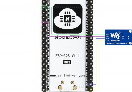

| ESP32 | MLX90640 Thermal Camera |
|---|---|
| 5V | 5V |
| GND | GND |
| SDA(P21) | SDA |
| SCL(P22) | SCL |
