
Difference between revisions of "Template:Compute module poe board manual"
From Waveshare Wiki
| Line 37: | Line 37: | ||
*Wait for several seconds to start Raspbian. | *Wait for several seconds to start Raspbian. | ||
===Connect HDMI display=== | ===Connect HDMI display=== | ||
| + | Here we use 7inch HDMI LCD (H) as examples | ||
| + | * Remove the DSI display if you have connected. Connect the HDMI display to PoE board (both HDMI interface and Touch interface should be connected) | ||
| + | * Modify /boot/config.txt fuke: | ||
| + | <pre> | ||
| + | max_usb_current=1 | ||
| + | hdmi_force_hotplug=1 | ||
| + | config_hdmi_boost=10 | ||
| + | hdmi_group=2 | ||
| + | hdmi_mode=87 | ||
| + | hdmi_cvt 1024 600 60 6 0 0 0 | ||
| + | </pre> | ||
| + | *Reboot | ||
| + | ===Connect CSI camera=== | ||
| + | ; 1. Test camera with pre-configured image | ||
| + | : 【Note】: Unlike the official Compute Module IO Board V3, the camera pins of this Compute PoE Module are not conflicted with 40Pin GPIO. | ||
| + | *Download the pre-configured image from Waveshare wiki. The image was pre-configured to use two cameras | ||
| + | *Connect RPi FPC camera to PoE board | ||
| + | *Power on PoE board and test camera | ||
| + | *Test the camera 1 | ||
| + | sudo raspivid -t 0 -cs 0 | ||
| + | *Test camera 2 | ||
| + | sudo raspivid -t 0 -cs 1 | ||
| + | 【Note】:-cs is used to choose camera 0 or 1; 0 for CAM1 and 1 for CAM0, | ||
| + | ;2. Test camera with original image | ||
| + | : If you use the original Raspbian image, you should configure an image for using the camera manually. | ||
| + | * Modify /boot/config.txt file, add statement to it | ||
| + | dtparam=arm_i2c | ||
| + | *Run commmand '''sudo raspi-config'''. choose Interfacing Options -> Camera -> Yes | ||
| + | *Download dts file from [https://www.raspberrypi.org/documentation/hardware/computemodule/dt-blob-disp1-cam2.dts Raspberry Pi website], and copy it to Rasbian | ||
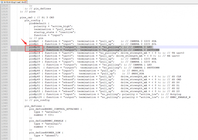
| + | *After downloading, modify the dts file | ||
| + | :[[File:Compute_Module_PoE_Board_User_Manual-13_.png|800px]] | ||
| + | :[[File:Compute_Module_PoE_Board_User_Manual-14.png|800px]] | ||
| + | :That is you should change LDE and SHUTDOWN from pin2, pin3 to pin32 and pin33. | ||
| + | *After modifying, you need to compile it | ||
| + | dtc -I dts -O dtb -o dt-blob.bin dt-blob-dualcam.dts | ||
| + | *To test camera, you can use commands below: | ||
| + | <pre> | ||
| + | sudo raspivid -t 0 -cs 0 | ||
| + | sudo raspivid -t 0 -cs 1 | ||
| + | </pre> | ||
| + | ===Connect colling fan=== | ||
Revision as of 10:07, 3 December 2019
Power
- 1. PoE power
- To enable POE function, you should set the PoE jumpers to EN side

- When using PoE function, this module supports 27V ~ 57V input, and voltage output is 5V and 2.5V.
- To check PoE, you can test pad 24.

- You can measure the voltage of pad 24 by multimeter, if the voltage is about 5.25V, the PoE function works normally, otherwise, it doesn't.
- 2. DC power

- Except PoE, you can also power on the Compute PoE board by DC 5V 2A (or above) power adapter. Connect Power adapter to Power interface.
Write image
- 1. If you use Compute Module 3 or Compute Module 3+, you should write an image to the internal eMMC
- Run rpiboot_setuo ( please download it from #Resource) to install driver. After installing, you will get an rpiboot.exe file in the installation directory.

- Set jumpers 20 to left side, set jumpers 22 and jumpers to left side as well.

- Insert your Compute module to PoE board.
- Connect SLAVR interface of PoE board to your PC
- Connect Power interface of PoE board to power adapter
- Run rpiboot.exe file, PC will recognize eMMC of Compute module as a portable drive.
- Run WinDiskImager.exe software to write image to eMMC.
【Note】
- While writing image, DO NOT write other portable storage drive to avoid conflicting. The EMMC of CM3+ is extended, which allows CM3+ to install common desktop image. Because EMMC of CM3 is only 4G, therefore if you want to write image to CM3, please choose Raspbian Lite. You can also install GUI for Lite image separately by commands below (network is required)
sudo apt-get update
sudo apt-get install raspberrypi-ui-mods
- 2. If you use Compute Module 3 Lite or Compute Module 3+ Lite, you should write the image to SD card just like common Raspberry Pi
- To write image, you should prepare an SD card (16G or larget) and card reader.
- Use Win32DiskImage.exe software to write image to SD card. (It is same as how you write image for Pi 3B)
- After writing, insert the SD card to the card slot of IO Board.
Connect DSI display
Here we use 4.3inch DSI LCD for example, you can also use official 7inch LCD.
- Please power off PoE board
- Connect 15Pin FPC cable to Compute Module PoE Board and DSI display'
- Connect power adapter to PoE board
- Wait for several seconds to start Raspbian.
Connect HDMI display
Here we use 7inch HDMI LCD (H) as examples
- Remove the DSI display if you have connected. Connect the HDMI display to PoE board (both HDMI interface and Touch interface should be connected)
- Modify /boot/config.txt fuke:
 max_usb_current=1
 hdmi_force_hotplug=1
 config_hdmi_boost=10
 hdmi_group=2
 hdmi_mode=87
 hdmi_cvt 1024 600 60 6 0 0 0
- Reboot
Connect CSI camera
- 1. Test camera with pre-configured image
- 【Note】: Unlike the official Compute Module IO Board V3, the camera pins of this Compute PoE Module are not conflicted with 40Pin GPIO.
- Download the pre-configured image from Waveshare wiki. The image was pre-configured to use two cameras
- Connect RPi FPC camera to PoE board
- Power on PoE board and test camera
- Test the camera 1
sudo raspivid -t 0 -cs 0
- Test camera 2
sudo raspivid -t 0 -cs 1
【Note】:-cs is used to choose camera 0 or 1; 0 for CAM1 and 1 for CAM0,
- 2. Test camera with original image
- If you use the original Raspbian image, you should configure an image for using the camera manually.
- Modify /boot/config.txt file, add statement to it
dtparam=arm_i2c
- Run commmand sudo raspi-config. choose Interfacing Options -> Camera -> Yes
- Download dts file from Raspberry Pi website, and copy it to Rasbian
- After downloading, modify the dts file

- That is you should change LDE and SHUTDOWN from pin2, pin3 to pin32 and pin33.


- After modifying, you need to compile it
dtc -I dts -O dtb -o dt-blob.bin dt-blob-dualcam.dts
- To test camera, you can use commands below:
sudo raspivid -t 0 -cs 0
sudo raspivid -t 0 -cs 1