Difference between revisions of "Template:CM4-IO-BASE-C Specification"
(→Note) |
|||
| (12 intermediate revisions by the same user not shown) | |||
| Line 1: | Line 1: | ||
=Overview= | =Overview= | ||
| − | This is the basic IO board of the 4th generation of Raspberry Pi Compute Module. CM4-IO-BASE-C is a carrier board that can be used with Raspberry Pi Compute Module 4. | + | This is the basic IO board of the 4th generation of Raspberry Pi Compute Module. CM4-IO-BASE-C is a carrier board that can be used with Raspberry Pi Compute Module 4. With a dedicated 40PIN LCD Connector, it also is easier and faster to be integrated into applications. |
| + | |||
| + | ==Versions== | ||
| + | *V1<br/> | ||
| + | [[File:CM4-IO-BASE-1.jpg]]<br/> | ||
| + | <!-- | ||
| + | *Compute_Module 4 | ||
| + | [[File:Compute Module 4 IO Board 5,png.png]]--> | ||
| + | *V2 (it will be updated based on this version in the future, and the V1 will stop updating.) | ||
| + | [[File:CM4-IO-BASE-C2.jpg]]<br/> | ||
==Note== | ==Note== | ||
<font color="#FF0000">1. Do not unplug any devices except USB and HDMI when powering on.</font><br/> | <font color="#FF0000">1. Do not unplug any devices except USB and HDMI when powering on.</font><br/> | ||
| Line 12: | Line 21: | ||
<font color="#FF0000">9. USB2.0 is closed by default, and you need to add "dtoverlay=dwc2,dr_mode=host" in "config.txt" when using.</font><br/> | <font color="#FF0000">9. USB2.0 is closed by default, and you need to add "dtoverlay=dwc2,dr_mode=host" in "config.txt" when using.</font><br/> | ||
10. This expansion board does not support POE function.<br/> | 10. This expansion board does not support POE function.<br/> | ||
| − | |||
==Dimensions== | ==Dimensions== | ||
| − | *CM4-IO-BASE-C<br/> | + | *CM4-IO-BASE-C-V1<br/> |
| − | [[File:CM4-IO-BASE-C01.jpg]]<br/> | + | [[File: CM4-IO-BASE-C01.jpg]]<br/> |
| − | *Compute_Module 4 | + | *CM4-IO-BASE-C-V2 |
| − | [[File:Compute Module 4 IO Board 5,png.png]]<br/> | + | [[File:CM4-IO-BASE-C4.jpg]]<br/> |
| + | *Compute_Module 4 | ||
| + | [[File: Compute Module 4 IO Board 5,png.png]]<br/> | ||
==Onboard Resources== | ==Onboard Resources== | ||
| + | ===CM4-IO-BASE-C V1=== | ||
[[File:CM4-IO-BASE-C03.jpg]]<br/> | [[File:CM4-IO-BASE-C03.jpg]]<br/> | ||
{|border=2; style="width:800px;" | {|border=2; style="width:800px;" | ||
| Line 63: | Line 74: | ||
|-align="center" | |-align="center" | ||
|19||RTC Battery Connection Socket||For connecting to CR1220 button cells | |19||RTC Battery Connection Socket||For connecting to CR1220 button cells | ||
| + | || | ||
| + | |} | ||
| + | |||
| + | ===CM4-IO-BASE-C V2=== | ||
| + | [[File:CM4-IO-BASE-C004.jpg]]<br/> | ||
| + | {|border=2; style="width:800px;" | ||
| + | |-style="background:#efffff; color:blue;" align="center" | ||
| + | |style="width:58px"|Number||Name||Description | ||
| + | |-style="background:#00eecc; color:blue;" align="center" | ||
| + | |-align="center" | ||
| + | |1||CM4 Socket||For all variants of Compute Module 4 | ||
| + | |-align="center" | ||
| + | |style="width:66px"|2||Power Supply/Programming Interface||5V/2.5A power supply, or used as the eMMC programming interface | ||
| + | |-align="center" | ||
| + | |3||LCD Port||40PIN LCD display port, for direct connection to 70H-1024600 series display | ||
| + | |-align="center" | ||
| + | |4||FAN Header||For connecting to the cooling fan with 5V, support speed adjustment and measurement | ||
| + | |-align="center" | ||
| + | |5||CAM Interface||Dual-channel MIPI CSI interface | ||
| + | |-align="center" | ||
| + | |6||HDMI0 Port||HDMI interface, for supporting 4K 30fps output | ||
| + | |-align="center" | ||
| + | |7||USB 2.0 Port||2-ch USB 2.0 port and support all kinds of USB devices | ||
| + | |-align="center" | ||
| + | |8||Gigabit Ethernet port||RJ45 Gigabit Ethernet port, support 10 / 100 / 1000M network access | ||
| + | |-align="center" | ||
| + | |9||M.2 Interface Indicator||Indicating the working status | ||
| + | |-align="center" | ||
| + | |10||LED Indicator||Red LED: ACT, indicating the operating status of Raspberry Pi<br>Green LED: PWR, indicating the status of Raspberry Pi power supply | ||
| + | |-align="center" | ||
| + | |11||BOOT||ON: CM4 would be booted from USB-C interface<br/>OFF: CM4 would be booted from eMMC or TF card | ||
| + | |-align="center" | ||
| + | |12||40PIN GPIO header||for connecting sorts of HAT | ||
| + | |-align="center" | ||
| + | |13||Micro SD Card Slot||for connecting an SD card with a pre-burnt image (Lite variant ONLY) | ||
| + | |-align="center" | ||
| + | |14||FE1.1S||USB HUB chip, USB interface 1 expansion 4 | ||
| + | |-align="center" | ||
| + | |15||M.2 Slot||supports sorts of NVME Solid State Drives or communication modules with PCIE M.2 KEY-M interface | ||
| + | |-align="center" | ||
| + | |16||RTC Chip||allows RTC-related functions like wakeup, shutdown, reboot, and more | ||
| + | |-align="center" | ||
| + | |17||RTC Interrupt Selection||GN-EN: CM4 shutdown(by default) on RTC interruption<br/>PI-RUN: CM4 reboot on RTC interruption<br/>D4: D4 pin is triggered on RTC interruption | ||
| + | |-align="center" | ||
| + | |18||RTC Battery Holder||supports CR1220 button cell | ||
|| | || | ||
|} | |} | ||
Latest revision as of 08:41, 29 January 2023
Overview
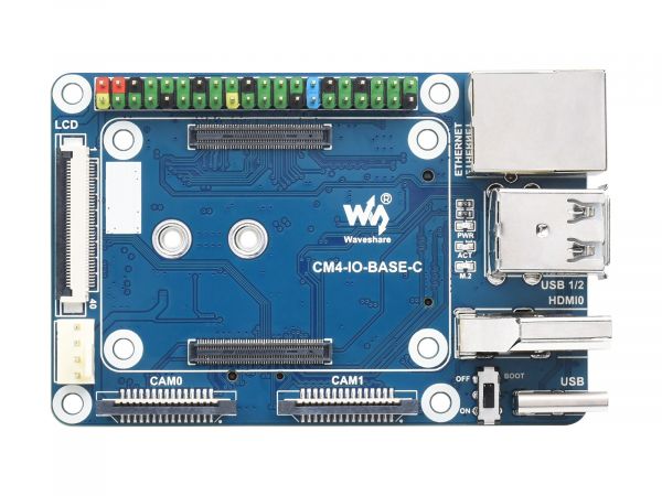
This is the basic IO board of the 4th generation of Raspberry Pi Compute Module. CM4-IO-BASE-C is a carrier board that can be used with Raspberry Pi Compute Module 4. With a dedicated 40PIN LCD Connector, it also is easier and faster to be integrated into applications.
Versions
- V1
- V2 (it will be updated based on this version in the future, and the V1 will stop updating.)
Note
1. Do not unplug any devices except USB and HDMI when powering on.
2. Only support fans with 5V, and 12V is not supported. Please check the voltage of the fan before connecting.
3. Only support LCD direct connection as there is not a DSI interface.
4. Type C interface can be used as the power supply or the USB SLAVE for programming images.
5. In order to ensure the power supply of the CM4, please do not connect to other devices when programming the images with the TypeC interface.
6. When using CM4, you must provide 5V 2A for it, otherwise, it may shut down, lower frequency or etc.
7. Please use the matching screws when using the M.2 interface as CM4 may be damaged if you use other screws.
8. The module does not have any protection, please do not short-circuit the power supply.
9. USB2.0 is closed by default, and you need to add "dtoverlay=dwc2,dr_mode=host" in "config.txt" when using.
10. This expansion board does not support POE function.
Dimensions
- CM4-IO-BASE-C-V1
- CM4-IO-BASE-C-V2
- Compute_Module 4
Onboard Resources
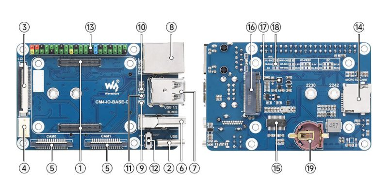
CM4-IO-BASE-C V1
| Number | Name | Description | |
| 1 | CM4 Socket | For all variants of Compute Module 4 | |
| 2 | Power Supply/Programming Interface | 5V/2.5A power supply, or used as the eMMC programming interface | |
| 3 | LCD Interface | 40PIN LCD display port, for direct connection to 70H-1024600 series display | |
| 4 | FAN header | For connecting to the cooling fan with 5V, support speed adjustment and measurement | |
| 5 | CAM Interface | Dual-channel MIPI CSI | |
| 6 | HDMI0 Interface | HDMI interface, for supporting 4K 30fps output | |
| 7 | USB 2.0 Interface | 2-ch USB2.0 and support all kinds of USB devices | |
| 8 | Gigabit Ethernet port | RJ45 Gigabit Ethernet port, support 10 / 100 / 1000M network access | |
| 9 | M.2 Interface Indicator | Indicating the working status | |
| 10 | PWR Indicator | Indicating the Raspberry Pi power status | |
| 11 | Status Indicators | Indicating the working status of the Raspberry Pi | |
| 12 | BOOT | Jumper cap connected: CM4 Type C booting guide Jumper cap not connected: eMMc or SD card booting guide | |
| 13 | 40PIN GPIO Header | For connecting all kinds of HAT | |
| 14 | Micro SD Card Interface | For connecting to a Micro SD card with the system, only for the Lite version | |
| 15 | FE1.1S | USB HUB chip, expand USB interface to 4 | |
| 16 | M.2 Interface | For NVIE SSD, or support PCIE M.2 communication module | |
| 17 | RTC Chip | PCF85063 chip, can be used for RTC wake-up, shutdown, restart, or other functions | |
| 18 | RTC Interrupt Selection | PI-RUN:RTC triggers interrupt CM4 restarts GN-EN:RTC trigger interrupt CM4 shutdown D4:RTC trigger interrupt D4 pin trigger | |
| 19 | RTC Battery Connection Socket | For connecting to CR1220 button cells |
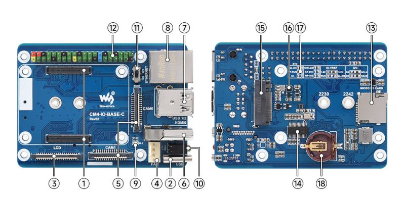
CM4-IO-BASE-C V2
| Number | Name | Description | |
| 1 | CM4 Socket | For all variants of Compute Module 4 | |
| 2 | Power Supply/Programming Interface | 5V/2.5A power supply, or used as the eMMC programming interface | |
| 3 | LCD Port | 40PIN LCD display port, for direct connection to 70H-1024600 series display | |
| 4 | FAN Header | For connecting to the cooling fan with 5V, support speed adjustment and measurement | |
| 5 | CAM Interface | Dual-channel MIPI CSI interface | |
| 6 | HDMI0 Port | HDMI interface, for supporting 4K 30fps output | |
| 7 | USB 2.0 Port | 2-ch USB 2.0 port and support all kinds of USB devices | |
| 8 | Gigabit Ethernet port | RJ45 Gigabit Ethernet port, support 10 / 100 / 1000M network access | |
| 9 | M.2 Interface Indicator | Indicating the working status | |
| 10 | LED Indicator | Red LED: ACT, indicating the operating status of Raspberry Pi Green LED: PWR, indicating the status of Raspberry Pi power supply | |
| 11 | BOOT | ON: CM4 would be booted from USB-C interface OFF: CM4 would be booted from eMMC or TF card | |
| 12 | 40PIN GPIO header | for connecting sorts of HAT | |
| 13 | Micro SD Card Slot | for connecting an SD card with a pre-burnt image (Lite variant ONLY) | |
| 14 | FE1.1S | USB HUB chip, USB interface 1 expansion 4 | |
| 15 | M.2 Slot | supports sorts of NVME Solid State Drives or communication modules with PCIE M.2 KEY-M interface | |
| 16 | RTC Chip | allows RTC-related functions like wakeup, shutdown, reboot, and more | |
| 17 | RTC Interrupt Selection | GN-EN: CM4 shutdown(by default) on RTC interruption PI-RUN: CM4 reboot on RTC interruption D4: D4 pin is triggered on RTC interruption | |
| 18 | RTC Battery Holder | supports CR1220 button cell |


