
Difference between revisions of "TOF Laser Range Sensor"
| (39 intermediate revisions by 3 users not shown) | |||
| Line 1: | Line 1: | ||
| − | <div class=" | + | <div class="wiki-pages jet-green-color"> |
| − | |||
{{Infobox item | {{Infobox item | ||
| − | |img=[[File:540px-TOF-Laser-Range-Sensor-1.jpg|300px|alt=TOF-Laser-Range-Sensor|link=https://www.waveshare.com/TOF-Laser-Range-Sensor.htm | TOF Laser Range Sensor]] | + | |img=[[File:540px-TOF-Laser-Range-Sensor-1.jpg|300px|alt=TOF-Laser-Range-Sensor|{{Amazon_nolink|default={{#ifeq: {{#urlget:amazon|0}}|{{#urlget:Amazon|0}}| default|}}|url=link=https://www.waveshare.com/TOF-Laser-Range-Sensor.htm}} | TOF Laser Range Sensor]] |
|brief= | |brief= | ||
|caption=VL53L1X Distance Sensor | |caption=VL53L1X Distance Sensor | ||
|category=[[:Category:Modules|Modules]], [[:Category:Sensors|Sensors]], [[:Category:Light|Light]] | |category=[[:Category:Modules|Modules]], [[:Category:Sensors|Sensors]], [[:Category:Light|Light]] | ||
|brand=Waveshare | |brand=Waveshare | ||
| − | |{{#urlget:amazon|default}}=display | + | |{{#ifeq: {{#urlget:amazon|0}}|{{#urlget:Amazon|0}}| default|}}=display |
|website_cn=[http://www.waveshare.net/shop/TOF-Laser-Range-Sensor.htm 网站] | |website_cn=[http://www.waveshare.net/shop/TOF-Laser-Range-Sensor.htm 网站] | ||
|website_en=[http://www.waveshare.com/TOF-Laser-Range-Sensor.htm Website] | |website_en=[http://www.waveshare.com/TOF-Laser-Range-Sensor.htm Website] | ||
| Line 16: | Line 15: | ||
{{Product List|Modules/Sensors/Light}} | {{Product List|Modules/Sensors/Light}} | ||
}} | }} | ||
| − | + | = Introduction = | |
TOF Laser Range Sensor is one laser ranging sensor based on TOF (time of | TOF Laser Range Sensor is one laser ranging sensor based on TOF (time of | ||
flight). The measuring scope is 1cm~5m, and the range resolution is | flight). The measuring scope is 1cm~5m, and the range resolution is | ||
| − | 1mm | + | 1mm. The data update frequency is 10Hz; Adjustable FOV with the |
maximum field angle is 27°; Supports UART and CAN communication; | maximum field angle is 27°; Supports UART and CAN communication; | ||
Support the active and query output data; Support the multi-sensor | Support the active and query output data; Support the multi-sensor | ||
| − | cascade ranging; Support I/O complementary output | + | cascade ranging; Support I/O complementary output. |
| + | ==Feature== | ||
| + | * Based on TOF (Time of Flight) laser ranging technology. | ||
| + | * Support UART, CAN communication( UART and CAN shared interface). | ||
| + | * Measuring scope: 1cm~5m | ||
| + | * Adjustable field angle (FOV): 15~27° | ||
| + | * Support the output of distance, distance status dis status, signal strength, and other information. | ||
| + | * Supports two output methods: active output and query output. | ||
| + | * Support multi-module cascade. | ||
| + | * One-click upgrade firmware. | ||
| + | * 3.7~5.2V power supply with anti-reverse protection. | ||
| + | * Power consumption is about 290mW. | ||
| + | * 940nm laser in compliance with Class1 Standard stipulated in IEC 60825-1:2014 Version 3. | ||
| − | + | ==Specification== | |
| − | |||
| − | |||
| − | |||
| − | |||
| − | |||
| − | |||
| − | |||
| − | |||
| − | |||
| − | |||
| − | |||
| − | |||
| − | |||
| − | |||
| − | |||
| − | |||
| − | |||
| − | |||
<div style="margin:2px auto;float:left;"> | <div style="margin:2px auto;float:left;"> | ||
{| style="border-collapse: collapse;border:1px solid #cccccc;color: #5e5e5e;margin: auto;" | {| style="border-collapse: collapse;border:1px solid #cccccc;color: #5e5e5e;margin: auto;" | ||
|- | |- | ||
! style="border:1px solid #cccccc;text-align:center;padding:5px;" rowspan="3" | Typical Ranging Scope<br/>(0.01~5.00m) | ! style="border:1px solid #cccccc;text-align:center;padding:5px;" rowspan="3" | Typical Ranging Scope<br/>(0.01~5.00m) | ||
| − | | style="border:1px solid #cccccc;padding:5px;" | Short | + | | style="border:1px solid #cccccc;padding:5px;" | Short Distance: 0.012~2.16m |
|- | |- | ||
| − | | style="border:1px solid #cccccc;padding:5px;" | Medium | + | | style="border:1px solid #cccccc;padding:5px;" | Medium Distance:0.012~3.60m |
|- | |- | ||
| − | | style="border:1px solid #cccccc;padding:5px;" | Long | + | | style="border:1px solid #cccccc;padding:5px;" | Long Distance: 0.01~5.00m |
|- | |- | ||
! rowspan="3" style="border:1px solid #cccccc;text-align:center;padding:5px;" | Typical Ranging Precision | ! rowspan="3" style="border:1px solid #cccccc;text-align:center;padding:5px;" | Typical Ranging Precision | ||
| − | | style="border:1px solid #cccccc;padding:5px;" | Short | + | | style="border:1px solid #cccccc;padding:5px;" | Short Distance: Precision±1.0cm, Standard deviation<0.3cm |
|- | |- | ||
| − | | style="border:1px solid #cccccc;padding:5px;" | Medium | + | | style="border:1px solid #cccccc;padding:5px;" | Medium Distance: Precision±1.0cm, Standard deviation<1.5cm |
|- | |- | ||
| − | | style="border:1px solid #cccccc;padding:5px;" | Long | + | | style="border:1px solid #cccccc;padding:5px;" | Long Distance: Precision±1.5cm, Standard deviation<0.5cm@[0.01,3]m scope,<br/>Standard deviation<8cm@(3,5]m scope |
|- | |- | ||
| − | ! style="border:1px solid #cccccc;text-align:center;" | Measurement | + | ! style="border:1px solid #cccccc;text-align:center;" | Measurement Resolution |
| style="border:1px solid #cccccc;padding:5px;" | 1mm | | style="border:1px solid #cccccc;padding:5px;" | 1mm | ||
|- | |- | ||
| Line 70: | Line 63: | ||
|- | |- | ||
! rowspan="2" style="border:1px solid #cccccc;text-align:center;" | Communication Interface<br/>(UART/CAN) | ! rowspan="2" style="border:1px solid #cccccc;text-align:center;" | Communication Interface<br/>(UART/CAN) | ||
| − | | style="border:1px solid #cccccc;padding:5px;" | UART (Two interfaces can be | + | | style="border:1px solid #cccccc;padding:5px;" | UART (Two interfaces can be simultaneous as UART interface, electrical level of TTL signal line is 3.3V) |
|- | |- | ||
| − | | style="border:1px solid #cccccc;padding:5px;" | CAN (Two interfaces can be | + | | style="border:1px solid #cccccc;padding:5px;" | CAN (Two interfaces can be simultaneous as CAN interface) |
|- | |- | ||
| − | ! rowspan="2" style="border:1px solid #cccccc;text-align:center;padding:5px;" | | + | ! rowspan="2" style="border:1px solid #cccccc;text-align:center;padding:5px;" | Baud Rate |
| − | | style="border:1px solid #cccccc;padding:5px;" | | + | | style="border:1px solid #cccccc;padding:5px;" | UART: 115200~3000000bps (Default 921600bps) |
|- | |- | ||
| − | | style="border:1px solid #cccccc;padding:5px;" | | + | | style="border:1px solid #cccccc;padding:5px;" | CAN: 100000~3000000bps (Default 100000bps) |
|- | |- | ||
| − | ! style="border:1px solid #cccccc;text-align:center;padding:5px;" | Cascade | + | ! style="border:1px solid #cccccc;text-align:center;padding:5px;" | Cascade Support |
| − | | style="border:1px solid #cccccc;padding:5px;" | UART interface supports cascading up to 8 , CAN interface supports cascading up to 7 | + | | style="border:1px solid #cccccc;padding:5px;" | UART interface supports cascading up to 8, CAN interface supports cascading up to 7 |
|- | |- | ||
| − | ! style="border:1px solid #cccccc;text-align:center;padding:5px;" | | + | ! style="border:1px solid #cccccc;text-align:center;padding:5px;" | Power Supply |
| style="border:1px solid #cccccc;padding:5px;" | 3.7~5.2V | | style="border:1px solid #cccccc;padding:5px;" | 3.7~5.2V | ||
|- | |- | ||
! style="border:1px solid #cccccc;text-align:center;padding:5px;" | Power Consumption | ! style="border:1px solid #cccccc;text-align:center;padding:5px;" | Power Consumption | ||
| − | | style="border:1px solid #cccccc;padding:5px;" | Under UART active output and long distance measuring mode, voltage of power supply is | + | | style="border:1px solid #cccccc;padding:5px;" | Under UART active output and long-distance measuring mode, the voltage of power supply is |
Copyright © Nooploop Ltd. 2019. All Rights Reserved. | Copyright © Nooploop Ltd. 2019. All Rights Reserved. | ||
7 | 7 | ||
| − | 5.0V and current is 58mA. | + | 5.0V and the current is 58mA. |
|- | |- | ||
| − | ! style="border:1px solid #cccccc;text-align:center;padding:5px;" | | + | ! style="border:1px solid #cccccc;text-align:center;padding:5px;" | Weight |
| style="border:1px solid #cccccc;padding:5px;" | 2.7g | | style="border:1px solid #cccccc;padding:5px;" | 2.7g | ||
|- | |- | ||
! style="border:1px solid #cccccc;text-align:center;padding:5px;" | Dimension | ! style="border:1px solid #cccccc;text-align:center;padding:5px;" | Dimension | ||
| − | | style="border:1px solid #cccccc;padding:5px;" | 35.58 × 12 × 8.05mm (Length*Width*Height) | + | | style="border:1px solid #cccccc;padding:5px;" | 35.58 × 12 × 8.05mm (Length * Width * Height) |
|} | |} | ||
</div> | </div> | ||
<div class="sep0px"></div> | <div class="sep0px"></div> | ||
| − | + | ==Applications== | |
| − | * Unmanned aerial vehicle height setting,ceiling detection | + | * Unmanned aerial vehicle height setting, ceiling detection |
* Robot obstacle avoidance | * Robot obstacle avoidance | ||
* Measuring and detecting | * Measuring and detecting | ||
| Line 109: | Line 102: | ||
==Technology Overview== | ==Technology Overview== | ||
TOF is one absolute distance detecting technology, that is the sensor emits the near-infrared light to | TOF is one absolute distance detecting technology, that is the sensor emits the near-infrared light to | ||
| − | be debugged, and it will reflect after encountering the object. The sensor calculates the distance of subject | + | be debugged, and it will reflect after encountering the object. The sensor calculates the distance of the subject |
| − | being photographed | + | being photographed by calculating the time difference or phase difference for the emission and |
| − | reflection of light so as to produce | + | reflection of light so as to produce depth information. Compared with the binocular plan and 3D |
| − | structural light plan, TOF has the advantages of long working | + | structural light plan, TOF has the advantages of long working distances, wide application scenarios, and |
| − | high precision of long | + | high precision of long distances, etc. Therefore, it is always applied to personnel proximity detection, |
| − | robot obstacle avoidance, camera automatic focusing etc. The near-infrared light coming from the | + | robot obstacle avoidance, camera automatic focusing, etc. The near-infrared light coming from the sunlight in the outdoor environment will generate an impact on the measuring effect of the module. |
| − | |||
[[File:TOF-Laser-Range-Sensor-work.jpg|600px]] | [[File:TOF-Laser-Range-Sensor-work.jpg|600px]] | ||
| Line 124: | Line 116: | ||
===【Interface & Baudrate】=== | ===【Interface & Baudrate】=== | ||
| − | TOFSense supports two communication modes with configurations | + | TOFSense supports two communication modes with configurations UART and CAN.<br /> |
| − | *UARTThe communication baud rate setting range is as | + | *UARTThe communication baud rate setting range is as follows: |
{| class="wikitable" style="padding:5px;" | {| class="wikitable" style="padding:5px;" | ||
|- | |- | ||
! UART Baud Rate !! Note | ! UART Baud Rate !! Note | ||
|- | |- | ||
| − | | 115200,230400,460800,921600,1000000,1200000,2000000,3000000 || Baud Rate is 921600 in default | + | | 115200, 230400, 460800, 921600, 1000000, 1200000, 2000000, 3000000 || Baud Rate is 921600 in default |
|} | |} | ||
| − | *Under CAN output mode, the setting range of Baud rate shall be shown as: | + | *Under CAN output mode, the setting range of the Baud rate shall be shown as: |
{| class="wikitable" | {| class="wikitable" | ||
|- | |- | ||
! CAN Baud Rate !! Note | ! CAN Baud Rate !! Note | ||
|- | |- | ||
| − | | 100000,250000,500000,1000000,2000000,3000000 || Baud Rate is 1000000 in default | + | | 100000, 250000, 500000, 1000000, 2000000, 3000000 || Baud Rate is 1000000 in default |
|} | |} | ||
Interface data output mode setting:<br /> | Interface data output mode setting:<br /> | ||
| − | *Active | + | *Active Output: |
**The active output mode can only be used with a single module. In this mode, the module actively outputs measurement information at a frequency of 10 Hz. | **The active output mode can only be used with a single module. In this mode, the module actively outputs measurement information at a frequency of 10 Hz. | ||
| − | **The active output mode configuration is as shown | + | **The active output mode configuration is as shown below: <br />[[File:TOF-UART-Active-Output-setting.jpg|400px]] [[File:TOF-CAN-Active-Output-setting.jpg|400px]] |
| − | *Query | + | *Query Output: |
| − | **The query output mode can be used in single module and cascade connection. In this mode, the controller sends a query command containing the module ID to the desired query module, and the module can output one frame of measurement information. | + | **The query output mode can be used in a single module and cascade connection. In this mode, the controller sends a query command containing the module ID to the desired query module, and the module can output one frame of measurement information. |
**Query output mode configuration as shown below:<br />[[File:TOF-UART-Query-Output-setting.jpg|400px]] [[File:TOF-CAN-Query-Output-setting.jpg|400px]] | **Query output mode configuration as shown below:<br />[[File:TOF-UART-Query-Output-setting.jpg|400px]] [[File:TOF-CAN-Query-Output-setting.jpg|400px]] | ||
===【Distance Status】=== | ===【Distance Status】=== | ||
The module can output the current distance status, the user can perform the data processing with the | The module can output the current distance status, the user can perform the data processing with the | ||
| − | combination of distance | + | combination of distance status. The meaning of distance status is as follows: |
{| class="wikitable" style="padding:5px;" | {| class="wikitable" style="padding:5px;" | ||
|- | |- | ||
| Line 174: | Line 166: | ||
===【Signal Strength】=== | ===【Signal Strength】=== | ||
| − | Indicate the strength of current return signal, and the larger this value indicates the stronger the | + | Indicate the strength of the current return signal, and the larger this value indicates the stronger the |
return signal. | return signal. | ||
===【FOV】=== | ===【FOV】=== | ||
| − | *The field angle FOV determines the vision scope of TOFSense. The module can change the field angle at X direction fov.x, field angle at Y direction fov.y, offset at X direction fov.x_offset and offset at Y direction fov.y_offset. The setting scope for field angle at X, Y directions is 15°~27°. The setting scope of offset for field angle at X, Y directions is -6°~ 6°. | + | *The field angle FOV determines the vision scope of TOFSense. The module can change the field angle at X direction fov.x, field angle at Y direction fov.y, offset at X direction fov.x_offset and offset at Y direction fov.y_offset. The setting scope for field angle at X, and Y directions is 15°~27°. The setting scope of offset for field angle at X, Y directions is -6°~ 6°. |
| − | *Module initial field of view parameters:fov.x= | + | *Module initial field of view parameters: fov.x=27°, fov.y=27°, fov.x_offset=0°, fov.y_offset=0°.<br />By setting the X-direction field of view angle of 25°, Y-direction field of view angle of 15°, X-direction offset 1°, Y-direction offset -1°.<br />The area of interest of the module can be changed as shown in the figure below:<br />[[File:TOF-FOV-show-1.jpg|600px]] |
| − | ''Note: A smaller FOV can improve the detection performance of the module in a small space and small objects, but the change of the FOV field of view will also affect the | + | ''Note: A smaller FOV can improve the detection performance of the module in a small space and small objects, but the change of the FOV field of view will also affect the module's farthest ranging distance.The smaller the field of view, the smaller the farthest ranging distance.'' |
===【Indicator Light】=== | ===【Indicator Light】=== | ||
| − | *The indicator includes two flashing | + | *The indicator includes two flashing statuses in total, including the fast flash once per 0.1S and slow flash once per 1S. LED status and meaning are as follows: |
{| class="wikitable" | {| class="wikitable" | ||
|- | |- | ||
| Line 198: | Line 190: | ||
===【Function Key】=== | ===【Function Key】=== | ||
| − | * It is used for the parameter setup under CAN communication mode. Press the power-on key until the indicator has | + | * It is used for the parameter setup under CAN communication mode. Press the power-on key until the indicator has a slow flash, and then compulsively enter UART configuration mode. This operation will not change the module setting parameter. If changing the module setup, it is required to rewrite the parameter. |
===【CascadeRanging】=== | ===【CascadeRanging】=== | ||
| Line 216: | Line 208: | ||
*TOFSense _UART_Frame: | *TOFSense _UART_Frame: | ||
| − | **'''Data | + | **''' Data Sources:''' Connect the module to the host computer and configure the UART as active output mode. |
| − | **'''Raw | + | **'''Raw data:''' |
57 00 ff 00 9e 8f 00 00 ad 08 00 00 03 00 ff 3a | 57 00 ff 00 9e 8f 00 00 ad 08 00 00 03 00 ff 3a | ||
| − | **'''Analysis | + | **'''Analysis table:'''<br /> |
{| class="wikitable" | {| class="wikitable" | ||
|- | |- | ||
| Line 246: | Line 238: | ||
*TOFSense _UART_Read_Frame: | *TOFSense _UART_Read_Frame: | ||
| − | **'''Data | + | **''' Data Sources:''' Connect the module to the host computer, configure it as UART query output mode, id is 0, and send the following data through the host computer to achieve data query. |
| − | **'''Raw | + | **'''Raw data:''' |
57 10 FF FF 00 FF FF 63 | 57 10 FF FF 00 FF FF 63 | ||
| − | **'''Analysis | + | **'''Analysis table:'''<br /> |
{| class="wikitable" | {| class="wikitable" | ||
|- | |- | ||
| Line 268: | Line 260: | ||
*TOFSense _CAN_Frame: | *TOFSense _CAN_Frame: | ||
| − | **'''Data | + | **''' Data Sources:''' The module is configured as CAN active output mode, id is 1, connect to CAN receiving device. |
| − | **'''Raw | + | **'''Raw data:''' |
AD 08 00 00 03 00 FF FF | AD 08 00 00 03 00 FF FF | ||
| − | **'''Analysis | + | **'''Analysis table:'''<br /> |
{| class="wikitable" | {| class="wikitable" | ||
|- | |- | ||
| Line 308: | Line 300: | ||
*TOFSense _CAN_Read_Frame: | *TOFSense _CAN_Read_Frame: | ||
| − | **'''Data source:''' The module is configured in CAN query output mode, id is 1, connected to CAN query device, and id_s is configured as 2。 | + | **''' Data source:''' The module is configured in CAN query output mode, id is 1, connected to CAN query device, and id_s is configured as 2。 |
| − | **'''Date | + | **''' Date Sources:''' |
FF FF FF 01 FF FF FF FF | FF FF FF 01 FF FF FF FF | ||
| − | **'''Analysis | + | **'''Analysis table:'''<br /> |
{| class="wikitable" | {| class="wikitable" | ||
|- | |- | ||
| Line 346: | Line 338: | ||
*TOFSense _Setting_Frame: | *TOFSense _Setting_Frame: | ||
| − | **'''Analysis | + | **'''Analysis table:'''<br /> |
[[File:TOFSense-Setting-table.png|800px]] | [[File:TOFSense-Setting-table.png|800px]] | ||
==Software== | ==Software== | ||
| − | + | TOF Assistant is the accessory debug software for TOFSense with the main functions: debug | |
| − | configuration, | + | configuration, status display, function application, and firmware upgrade: |
| − | *Debug configuration: Used for configuring the relevant parameters of nodes, e.g. ID, working | + | *'''Debug configuration:''' Used for configuring the relevant parameters of nodes, e.g. ID, working mode, baud rate, etc. |
| − | mode, | + | *''' Function application:''' Used for the application development, e.g. data import and export, motion trail storage, historical trial replay, etc. |
| − | *Function application: Used for the application development, e.g. data import and export, motion | + | *'''Firmware upgrade:''' Used for carrying out the wired firmware upgrade for the product. |
| − | trail storage, historical trial replay etc. | + | *Hardware connection reference (you also need a USB TO TTL module): |
| − | *Firmware upgrade: Used for carrying out the wired firmware upgrade for product. | ||
| − | |||
| − | *Hardware connection reference(you also need a USB TO TTL module) | ||
[[File:TOF-Connect.jpg|800px]]<br /> | [[File:TOF-Connect.jpg|800px]]<br /> | ||
| − | *Software setup | + | *Software setup video:<br /> |
| − | |||
[[File:TOF-Setting.mp4]] | [[File:TOF-Setting.mp4]] | ||
==Dimensions== | ==Dimensions== | ||
*[[File:900px-TOF-Laser-Range-Sensor-details-size.jpg|600px]] | *[[File:900px-TOF-Laser-Range-Sensor-details-size.jpg|600px]] | ||
| − | + | ||
| − | ===Hardware connection | + | =Working with Raspberry Pi= |
| + | ==Environment Debugging== | ||
| + | *Raspberry Pi Serial Port Setting | ||
| + | Due to the serial port of the Raspberry Pi being for terminal debugging by default, you need to modify the Raspberry Pi setting when using the serial port. Please execute the following demand to enter the Raspberry Pi setting: | ||
| + | sudo raspi-config | ||
| + | Choose Interfacing Options -> Serial -> no -> yes and close the serial debugging function.<br/> | ||
| + | [[File:TOF Laser Range Sensor01.jpg]]<br/> | ||
| + | Reboot: <br/> | ||
| + | sudo reboot | ||
| + | Open the /boot/config.txt file, and find the following configuration statement to enable the serial port, if not, add it at the end of the file:<br/> | ||
| + | enable_uart=1 | ||
| + | Reboot it to take effect.<br/> | ||
| + | |||
| + | ==Hardware connection== | ||
[[File:TOF-Laser-Range-Sensor-Pi-connected.jpg|800px]] | [[File:TOF-Laser-Range-Sensor-Pi-connected.jpg|800px]] | ||
===Software settings=== | ===Software settings=== | ||
| − | Module baud rate | + | Module baud rate setting: 115200. <br /> |
[[File:TOF Laser Range Sensor raspberry1.jpg|800px]] | [[File:TOF Laser Range Sensor raspberry1.jpg|800px]] | ||
| − | + | =Working with Jetson Nano= | |
| − | + | ==Hardware Connection== | |
| − | [[File: | + | [[File: Tof-jetson.png|800px]] |
| − | + | ||
| − | Module baud rate | + | ==Software settings== |
| + | Module baud rate setting: 115200 <br /> | ||
[[File:TOF-setting-1.png|800px]]<br />[[File:TOF-setting-2.png|400px]] | [[File:TOF-setting-1.png|800px]]<br />[[File:TOF-setting-2.png|400px]] | ||
[[File:TOF Laser Range Sensor jetson Demo.png|800px]] | [[File:TOF Laser Range Sensor jetson Demo.png|800px]] | ||
| − | + | =Working with Arduino= | |
| − | + | ==Hardware connection== | |
[[File:TOF-Laser-Range-Sensor-Arduino-connected.jpg|800px]] | [[File:TOF-Laser-Range-Sensor-Arduino-connected.jpg|800px]] | ||
| − | + | ==Software settings== | |
| − | Module baud rate | + | Module baud rate setting: 115200 <br /> |
[[File:TOF-setting-2.png|400px]] | [[File:TOF-setting-2.png|400px]] | ||
[[File:TOF-Arduino-Test.jpg|800px]] | [[File:TOF-Arduino-Test.jpg|800px]] | ||
| − | + | = Resources = | |
| − | + | ==Demo code== | |
| − | *[ | + | *[https://files.waveshare.com/upload/f/f7/TOF-Laser-Range-Sensor-Demo.7z Demo code] |
| − | + | ||
| − | + | ==Software== | |
| − | + | *[https://files.waveshare.com/upload/2/23/Waveshare_TOFAssistant.zip TOF Assistant PC Assistant (Windows 7/10 64-bit machine)] | |
| − | *[ | + | *[https://files.waveshare.com/upload/9/96/Waveshare_TOFAssistant_32bit.zip TOF AssistantPC Assistant (Windows 7/10 32-bit machine)] |
| − | *[ | + | |
| − | + | =FAQ= | |
| − | + | {{FAQ|Can it be used under outdoor (strong light) conditions? | |
| − | |||
| − | {{FAQ|Can it be used under outdoor ( | ||
|The module is affected by natural light. Generally speaking, the stronger the natural light, the greater the impact, which manifests as the shorter the ranging distance, the worse the accuracy, and the larger the fluctuation. Under strong light conditions (such as sunlight), it is generally recommended to use in close-range detection scenes.}} | |The module is affected by natural light. Generally speaking, the stronger the natural light, the greater the impact, which manifests as the shorter the ranging distance, the worse the accuracy, and the larger the fluctuation. Under strong light conditions (such as sunlight), it is generally recommended to use in close-range detection scenes.}} | ||
{{FAQ|Is there interference in the work of multiple modules? | {{FAQ|Is there interference in the work of multiple modules? | ||
|No interference. When multiple modules work at the same time, even if the infrared rays between each other cross or hit the same position, it will not affect the actual measurement.}} | |No interference. When multiple modules work at the same time, even if the infrared rays between each other cross or hit the same position, it will not affect the actual measurement.}} | ||
{{FAQ|Why is there no data output in TOFSense? | {{FAQ|Why is there no data output in TOFSense? | ||
| − | |Each module is shipped after strict testing. If there is no data, please check whether the mode, wiring, baud rate and other configurations are correct; for CAN output mode, please check whether it contains a terminal resistance (usually 120Ω).}} | + | |Each module is shipped after strict testing. If there is no data, please check whether the mode, wiring, baud rate, and other configurations are correct; for CAN output mode, please check whether it contains a terminal resistance (usually 120Ω).}} |
{{FAQ|What should I pay attention to when installing? | {{FAQ|What should I pay attention to when installing? | ||
|When installing, avoid obstruction in the FOV angle. In addition, attention should be paid to the height of the ground, and similar reflective surfaces such as ground occlusion in the FOV should be avoided.}} | |When installing, avoid obstruction in the FOV angle. In addition, attention should be paid to the height of the ground, and similar reflective surfaces such as ground occlusion in the FOV should be avoided.}} | ||
| Line 415: | Line 415: | ||
{{FAQ|How to configure the module for UART or CAN communication mode? | {{FAQ|How to configure the module for UART or CAN communication mode? | ||
|In the UART communication mode, the module can be configured to the CAN communication mode through the host computer; in the CAN communication mode, you need to press and hold the button and then power on the module. When the indicator light flashes slowly, release the button. When the module is forced to enter the UART mode, and then write the UART configuration through the host computer.}} | |In the UART communication mode, the module can be configured to the CAN communication mode through the host computer; in the CAN communication mode, you need to press and hold the button and then power on the module. When the indicator light flashes slowly, release the button. When the module is forced to enter the UART mode, and then write the UART configuration through the host computer.}} | ||
| − | {{FAQ|The shortest distance, the longest distance or the average distance when the module outputs? | + | {{FAQ|The shortest distance, the longest distance, or the average distance when the module outputs? |
|A single test volume of the module will get multiple sets of distance values, and the internal processor will process the largest distance.}} | |A single test volume of the module will get multiple sets of distance values, and the internal processor will process the largest distance.}} | ||
| + | {{FAQ|What is the I/O port working level of the module? | ||
| + | |3.3V | ||
| + | ||}} | ||
{{FAQ|Does the module support output point cloud information? | {{FAQ|Does the module support output point cloud information? | ||
| − | |The module can only output one distance at a time | + | |The module can only output one distance at a time and does not support the output of point cloud information temporarily.}} |
{{FAQ|If reports an error "The MSVC***.dll file cannot be found...". It may be that the computer lacks the corresponding runtime components of Microsoft.? | {{FAQ|If reports an error "The MSVC***.dll file cannot be found...". It may be that the computer lacks the corresponding runtime components of Microsoft.? | ||
| − | | [https://support.microsoft.com/en-us/help/2977003/the-latest-supported-visual-c-downloads Visual C ++ Redistributable for Visual Studio 2017], if the above installation fails or shows success, but opening the NAssistant program still prompts that the dll file is missing.Note, please select the patch for the computer system.}} | + | | [https://support.microsoft.com/en-us/help/2977003/the-latest-supported-visual-c-downloads Visual C ++ Redistributable for Visual Studio 2017], if the above installation fails or shows success, but opening the NAssistant program still prompts that the dll file is missing. Note, please select the patch for the computer system.}} |
{{FAQ| The software report an error "Because Qt***.dll cannot be found..."? | {{FAQ| The software report an error "Because Qt***.dll cannot be found..."? | ||
| − | |Please check whether the installation file is silently intercepted by security software , please exit the security software and reinstall it. Also run with administrator rights.}} | + | |Please check whether the installation file is silently intercepted by the security software, please exit the security software and reinstall it. Also, run with administrator rights.}} |
| − | + | =Support= | |
| − | + | {{Servicebox1}} | |
| − | |||
| − | |||
| − | {{ | ||
</div> | </div> | ||
Latest revision as of 02:47, 6 January 2024
| ||

Introduction
TOF Laser Range Sensor is one laser ranging sensor based on TOF (time of flight). The measuring scope is 1cm~5m, and the range resolution is 1mm. The data update frequency is 10Hz; Adjustable FOV with the maximum field angle is 27°; Supports UART and CAN communication; Support the active and query output data; Support the multi-sensor cascade ranging; Support I/O complementary output.
Feature
- Based on TOF (Time of Flight) laser ranging technology.
- Support UART, CAN communication( UART and CAN shared interface).
- Measuring scope: 1cm~5m
- Adjustable field angle (FOV): 15~27°
- Support the output of distance, distance status dis status, signal strength, and other information.
- Supports two output methods: active output and query output.
- Support multi-module cascade.
- One-click upgrade firmware.
- 3.7~5.2V power supply with anti-reverse protection.
- Power consumption is about 290mW.
- 940nm laser in compliance with Class1 Standard stipulated in IEC 60825-1:2014 Version 3.
Specification
| Typical Ranging Scope (0.01~5.00m) |
Short Distance: 0.012~2.16m |
|---|---|
| Medium Distance:0.012~3.60m | |
| Long Distance: 0.01~5.00m | |
| Typical Ranging Precision | Short Distance: Precision±1.0cm, Standard deviation<0.3cm |
| Medium Distance: Precision±1.0cm, Standard deviation<1.5cm | |
| Long Distance: Precision±1.5cm, Standard deviation<0.5cm@[0.01,3]m scope, Standard deviation<8cm@(3,5]m scope | |
| Measurement Resolution | 1mm |
| Wave Length | 940nm (Comply with Class 1 Standard in IEC 60825-1:2014 Version 3) |
| Field Angle (FOV) | 15°~27° (Multiple gears adjustable) |
| Communication Interface (UART/CAN) |
UART (Two interfaces can be simultaneous as UART interface, electrical level of TTL signal line is 3.3V) |
| CAN (Two interfaces can be simultaneous as CAN interface) | |
| Baud Rate | UART: 115200~3000000bps (Default 921600bps) |
| CAN: 100000~3000000bps (Default 100000bps) | |
| Cascade Support | UART interface supports cascading up to 8, CAN interface supports cascading up to 7 |
| Power Supply | 3.7~5.2V |
| Power Consumption | Under UART active output and long-distance measuring mode, the voltage of power supply is
Copyright © Nooploop Ltd. 2019. All Rights Reserved. 7 5.0V and the current is 58mA. |
| Weight | 2.7g |
| Dimension | 35.58 × 12 × 8.05mm (Length * Width * Height) |
Applications
- Unmanned aerial vehicle height setting, ceiling detection
- Robot obstacle avoidance
- Measuring and detecting
- Intelligent gesture control
- 1-dimension gesture identification
Technology Overview
TOF is one absolute distance detecting technology, that is the sensor emits the near-infrared light to be debugged, and it will reflect after encountering the object. The sensor calculates the distance of the subject being photographed by calculating the time difference or phase difference for the emission and reflection of light so as to produce depth information. Compared with the binocular plan and 3D structural light plan, TOF has the advantages of long working distances, wide application scenarios, and high precision of long distances, etc. Therefore, it is always applied to personnel proximity detection, robot obstacle avoidance, camera automatic focusing, etc. The near-infrared light coming from the sunlight in the outdoor environment will generate an impact on the measuring effect of the module.

Function description
【ID】
- ID is one variable set up for distinguishing the different sensors, which is used to identify each sensor during the cascade connection.
【Interface & Baudrate】
TOFSense supports two communication modes with configurations UART and CAN.
- UARTThe communication baud rate setting range is as follows:
| UART Baud Rate | Note |
|---|---|
| 115200, 230400, 460800, 921600, 1000000, 1200000, 2000000, 3000000 | Baud Rate is 921600 in default |
- Under CAN output mode, the setting range of the Baud rate shall be shown as:
| CAN Baud Rate | Note |
|---|---|
| 100000, 250000, 500000, 1000000, 2000000, 3000000 | Baud Rate is 1000000 in default |
Interface data output mode setting:
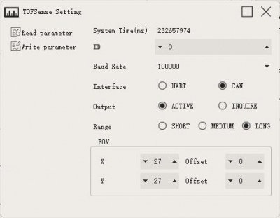
- Active Output:
- The active output mode can only be used with a single module. In this mode, the module actively outputs measurement information at a frequency of 10 Hz.
- The active output mode configuration is as shown below:


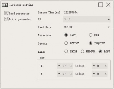
- Query Output:
- The query output mode can be used in a single module and cascade connection. In this mode, the controller sends a query command containing the module ID to the desired query module, and the module can output one frame of measurement information.
- Query output mode configuration as shown below:


【Distance Status】
The module can output the current distance status, the user can perform the data processing with the combination of distance status. The meaning of distance status is as follows:
| Value | Note |
|---|---|
| 0 | Measuring distance is valid |
| 1 | Standard deviation is more than 15mm |
| 2 | Signal strength is lower than 1Mcps |
| 4 | Phase exceeds boundary |
| 5 | HW or VCSEL has fault |
| 7 | Phase is not matched |
| 8 | Internal algorithm underflow |
| 14 | Measuring distance is invalid |
【Signal Strength】
Indicate the strength of the current return signal, and the larger this value indicates the stronger the return signal.
【FOV】
- The field angle FOV determines the vision scope of TOFSense. The module can change the field angle at X direction fov.x, field angle at Y direction fov.y, offset at X direction fov.x_offset and offset at Y direction fov.y_offset. The setting scope for field angle at X, and Y directions is 15°~27°. The setting scope of offset for field angle at X, Y directions is -6°~ 6°.
- Module initial field of view parameters: fov.x=27°, fov.y=27°, fov.x_offset=0°, fov.y_offset=0°.
By setting the X-direction field of view angle of 25°, Y-direction field of view angle of 15°, X-direction offset 1°, Y-direction offset -1°.
The area of interest of the module can be changed as shown in the figure below:

Note: A smaller FOV can improve the detection performance of the module in a small space and small objects, but the change of the FOV field of view will also affect the module's farthest ranging distance.The smaller the field of view, the smaller the farthest ranging distance.
【Indicator Light】
- The indicator includes two flashing statuses in total, including the fast flash once per 0.1S and slow flash once per 1S. LED status and meaning are as follows:
| Status | Note |
|---|---|
| Fast Flash (interval 0.1S) | Module starting stage |
| Fast Flash (interval 0.1S) | Module firmware update |
| Slow Flash (interval 1S) | Module normal working |
【Function Key】
- It is used for the parameter setup under CAN communication mode. Press the power-on key until the indicator has a slow flash, and then compulsively enter UART configuration mode. This operation will not change the module setting parameter. If changing the module setup, it is required to rewrite the parameter.
【CascadeRanging】
- Multiple sensors are configured with different IDs and connected in series, and the ranging information of all sensors can be read through one communication interface. The connection diagram is as follows:


Note: Under cascade ranging, it is suitable for UART query, CAN query, and CAN active output.。
Protocol analysis
- The protocol is composed of Frame Header, Function Mark, Data, and Sum Check.
- The Frame Header and Function Mark are fixed values;
- Data is the content of the transmitted data;
- Sum Check is the lowest byte after the addition of Frame Header, Function Mark, and Data (that is, the addition of all the previous bytes).
- Agreement composition:
Frame Header + Function Mark + Data + Sum Check
Note: Protocol packets follow the principle of little-endian mode, that is, the low byte is first and the high byte is last.
- TOFSense _UART_Frame:
- Data Sources: Connect the module to the host computer and configure the UART as active output mode.
- Raw data:
57 00 ff 00 9e 8f 00 00 ad 08 00 00 03 00 ff 3a
- Analysis table:
- Analysis table:
| Data | Type | Length (Bytes) | Hex | Result |
|---|---|---|---|---|
| Frame Header | uint8 | 1 | 57 | 0x57 |
| Function Mark | uint8 | 1 | 00 | 0x00 |
| reserved | uint8 | 1 | ff | * |
| id | uint8 | 1 | 00 | 0 |
| System_time | uint32 | 4 | 9e 8f 00 00 | 36766ms |
| dis*1000 | uint24 | 3 | ad 08 00 | 2.221m |
| dis_status | uint8 | 1 | 00 | 0 |
| signal_strength | uint16 | 2 | 03 00 | 3 |
| reserved | * | 1 | ... | * |
| Sum Check | uint8 | 1 | 3a | 0x3a |
- TOFSense _UART_Read_Frame:
- Data Sources: Connect the module to the host computer, configure it as UART query output mode, id is 0, and send the following data through the host computer to achieve data query.
- Raw data:
57 10 FF FF 00 FF FF 63
- Analysis table:
- Analysis table:
| Data | Type | Length (Bytes) | Hex | Result |
|---|---|---|---|---|
| Frame Header | uint8 | 1 | 57 | 0x57 |
| Function Mark | uint8 | 1 | 00 | 0x00 |
| reserved | uint8 | 2 | ff | * |
| id | uint8 | 1 | 00 | 0 |
| reserved | uint8 | 2 | ff | * |
| Sum Check | uint8 | 1 | 3a | 0x3a |
- TOFSense _CAN_Frame:
- Data Sources: The module is configured as CAN active output mode, id is 1, connect to CAN receiving device.
- Raw data:
AD 08 00 00 03 00 FF FF
- Analysis table:
- Analysis table:
| Field name | Part | Level | Type | Length(bits) | Hex | Result |
|---|---|---|---|---|---|---|
| Start Of Frame | SOF | * | 1 | * | * | |
| Arbitration Field | ID | * | 11 | 0x200+id | 0x201 | |
| Arbitration Field | RTR | * | 1 | * | * | |
| Control Field | IDE | * | 1 | * | * | |
| Control Field | r0 | * | 1 | * | * | |
| Control Field | DLC | * | 4 | * | * | |
| Data Field | dis*1000 | uint24 | 24 | ad 08 00 | 2.221m | |
| Data Field | dis_status | uint8 | 8 | 00 | 0 | |
| Data Field | signal_strength | uint16 | 16 | 03 00 | 3 | |
| Data Field | reserved | * | 16 | * | * | |
| CRC Field | CRC | * | 15 | * | * | |
| CRC Field | CRC_delimiter | * | 1 | * | * | |
| ACK Field | ACK Slot | * | 1 | * | * | |
| ACK Field | ACK_delimiter | * | 1 | * | * | |
| End Of Frame | EOF | * | 7 | * | * |
- TOFSense _CAN_Read_Frame:
- Data source: The module is configured in CAN query output mode, id is 1, connected to CAN query device, and id_s is configured as 2。
- Date Sources:
FF FF FF 01 FF FF FF FF
- Analysis table:
- Analysis table:
| Field name | Part | Level | Type | Length(bits) | Hex | Result |
|---|---|---|---|---|---|---|
| Start Of Frame | SOF | * | 1 | * | * | |
| Arbitration Field | ID | * | 11 | 0x400+id_s | 0x402 | |
| Arbitration Field | RTR | * | 1 | * | * | |
| Control Field | IDE | * | 1 | * | * | |
| Control Field | r0 | * | 1 | * | * | |
| Control Field | DLC | * | 4 | * | * | |
| Data Field | reserved | uint24 | * | * | * | |
| Data Field | id | uint8 | 8 | 01 | id = 1 | |
| Data Field | reserved | uint16 | * | * | * | |
| CRC Field | CRC | * | 15 | * | * | |
| CRC Field | CRC_delimiter | * | 1 | * | * | |
| ACK Field | ACK Slot | * | 1 | * | * | |
| ACK Field | ACK_delimiter | * | 1 | * | * | |
| End Of Frame | EOF | * | 7 | * | * |
- TOFSense _Setting_Frame:
- Analysis table:
- Analysis table:

Software
TOF Assistant is the accessory debug software for TOFSense with the main functions: debug configuration, status display, function application, and firmware upgrade:
- Debug configuration: Used for configuring the relevant parameters of nodes, e.g. ID, working mode, baud rate, etc.
- Function application: Used for the application development, e.g. data import and export, motion trail storage, historical trial replay, etc.
- Firmware upgrade: Used for carrying out the wired firmware upgrade for the product.
- Hardware connection reference (you also need a USB TO TTL module):

- Software setup video:
Dimensions

Working with Raspberry Pi
Environment Debugging
- Raspberry Pi Serial Port Setting
Due to the serial port of the Raspberry Pi being for terminal debugging by default, you need to modify the Raspberry Pi setting when using the serial port. Please execute the following demand to enter the Raspberry Pi setting:
sudo raspi-config
Choose Interfacing Options -> Serial -> no -> yes and close the serial debugging function.

Reboot:
sudo reboot
Open the /boot/config.txt file, and find the following configuration statement to enable the serial port, if not, add it at the end of the file:
enable_uart=1
Reboot it to take effect.
Hardware connection

Software settings
Module baud rate setting: 115200.

Working with Jetson Nano
Hardware Connection

Software settings
Module baud rate setting: 115200


Working with Arduino
Hardware connection

Software settings
Module baud rate setting: 115200

Resources
Demo code
Software
- TOF Assistant PC Assistant (Windows 7/10 64-bit machine)
- TOF AssistantPC Assistant (Windows 7/10 32-bit machine)
FAQ
{{{5}}}
{{{5}}}
{{{5}}}
{{{5}}}
{{{5}}}
{{{5}}}
{{{5}}}
{{{5}}}
{{{5}}}
{{{5}}}
{{{5}}}
Support
Technical Support
If you need technical support or have any feedback/review, please click the Submit Now button to submit a ticket, Our support team will check and reply to you within 1 to 2 working days. Please be patient as we make every effort to help you to resolve the issue.
Working Time: 9 AM - 6 AM GMT+8 (Monday to Friday)