| RPLIDAR A1
|

UART
|
|
|
|
|
|
|
|
|
|
|
|
|
Primary Attribute
|
|
|
| Category:
|
| {{{userDefinedInfo}}}:
|
{{{userdefinedvalue}}}
|
| Brand: Waveshare
|
|
|
|
|
Website
|
|
|
| International: [Website]
|
| Chinese: 官网
|
|
|
|
|
|
Overview
RPLIDAR A1 can perform a 360-degree scan within a 12-meter range. The produced 2D point cloud data can be used in mapping, localization, and object/environment modeling. The scanning frequency of RPLIDAR A1 reached 5.5hz when sampling 1450 points each round. And it can be configured up to 10hz① maximum.
RPLIDAR A1 is basically a laser triangulation measurement system. It can work excellently in all kinds of indoor environments and outdoor environments without direct sunlight exposure.
RPLIDAR A1 contains a range scanner system and a motor system. After power on each sub-system, RPLIDAR A1 starts rotating and scanning clockwise. Users can get range scan data through the communication interface (Serial port/USB).
Features
- Laser triangulation principle.
- Support UART communication.
- The measuring radius is 12m.
- 8000Hz measurement frequency.
- 360° scanning range.
- Laser Safety Meets Class 1 Standards.
Specification
| Typical Distance Range |
0.15~12m
|
| Sample Frequency |
8000 Hz
|
| Scan Rate |
5.5HZ
|
| Angular Resolution |
≤1°
|
| Mechanical Dimension |
96.8*70.3*55mm
|
| Communication Interface |
UART @ 115200bps
|
| Power |
5V
|
| Working Current |
100mA
|
| Power Consumption |
0.5W
|
| Working Temperature Range |
0℃~40℃
|
| Scan Range |
360°
|
| Ranging Accuracy |
1% of actual distance (≤3 m); 2% of actual distance (3-5 m); 2.5% of actual distance (5-12m)
|
Application
- Education and research
- Robot obstacle avoidance
- Measurement and inspection
- Smart gesture control
- 2D gesture recognition
- Autonomous navigation
- Map reconstruction
- Navigation and positioning
How to Work
The standard configuration of RPLIDAR A1 is using a 3.3V level serial port (UART) as the communication interface, and the other interfaces, such as USB, can be used according to customer needs. The following table is the specification information based on the serial interface:

| Item |
Unit |
Minimum |
Typical |
Maximum |
Note
|
| Baud Rate |
bps |
- |
115200* |
- |
-
|
| Working Mode |
- |
- |
8 data bits, 1 stop bit, no parity |
- |
8n1
|
| Output High Level Voltage |
V |
2.9 |
- |
3.5 |
output high level voltage value
|
| Output Low Level Voltage |
V |
- |
- |
0.4 |
output low level voltage value
|
| Input High Level Voltage |
V |
1.6* |
- |
3.5 |
input high level voltage value
|
| Input Low Level Voltage |
V |
-0.3 |
- |
0.4 |
input loew level voltage value
|
- Note: When using the radar adapter board, the default baud rate of the adapter board is 57600.
- Note: The RX input signal of A1M8 is controlled by the current, in order to ensure the internal signal identification, the actual control node voltage of the pin cannot be lower than 1.6V.
| Signal |
Type |
Description |
Minimum |
Typical value |
Maximum
|
| 5V_MOTO |
Power Supply |
RPLIDAR scan motor power supply |
- |
5V |
9V
|
| CTRL_MOTO |
Input |
RPLIDAR scan motor enable/PWM control signal (active high) |
0V |
- |
5V_Motor
|
| GND_MOTO |
Power Supply |
RPLIDAR scan motor ground |
- |
0V |
-
|
| VCC_5V |
Power Supply |
RPLIDAR ranging core power supply |
4.9V |
5V |
5.5V
|
| TX |
Output |
RPLIDAR ranging core serial output |
0V |
- |
5V
|
| RX |
Input |
RPLIDAR ranging core serial input |
0V |
- |
5V
|
| GND |
Power Supply |
RPLIDAR ranging core ground wire |
- |
0V |
V5.0
|
Host Computer Software
- frame_grabber.zip
- CP210x_Driver.zip
- Connect the adapter board to the computer via USB after connecting it to the radar.
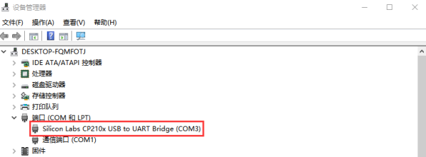
- Open the device manager and check the COM of the CP210x.

- If the device is not detected, you need to download CP210x_Driver.zip and install the driver.
- Download frame_grabber.zip and unzip it.
- Run the frame_grabber.exe in the compressed package, select the COM of the CP210X and the baud rate of 57600, and click OK.

- Click Start Scan in the upper left corner to get the scanning results.

- By now, you can see the results.
Resource
Document
2D Drawing
3D Module
SDK
ROS Package


