
Difference between revisions of "RP2040-LCD-1.28"
From Waveshare Wiki
(→Demo) |
|||
| Line 16: | Line 16: | ||
*[https://www.waveshare.com/w/upload/9/9d/RP2040-LCD-1.28.zip Demo code] | *[https://www.waveshare.com/w/upload/9/9d/RP2040-LCD-1.28.zip Demo code] | ||
*[https://github.com/dawigit/picoclock Clock project shared by Wienzek Daniel] | *[https://github.com/dawigit/picoclock Clock project shared by Wienzek Daniel] | ||
| + | *[https://github.com/PhilippMolitor/waveshare-rp2040-roundlcd-boilerplate Demo codes based on PlatformIO, shared by Philipp Molitor] | ||
==Drawing== | ==Drawing== | ||
Revision as of 09:58, 31 May 2023
| ||

Overview
RP2040-LCD-1.28 is a low-cost, high-performance MCU board designed by Waveshare. Although it is tiny, it incorporates a 1.28inch LCD round display, Li-ion battery charger, 6-axis sensor (3-axis accelerometer and 3-axis gyroscope), and so on, adapting all GPIO and Debug headers, which makes it easy for you to develop and integrate it into products quickly.
Feature
- RP2040 MCU chip designed by Raspberry Pi in the United Kingdom.
- Dual-core Arm Cortex M0+ processor, flexible clock running up to 133 MHz.
- 264KB of SRAM, and 2MB of onboard Flash memory.
- Type-C connector, keeps it up to date, easier to use.
- Onboard 1.28-inch 240 x 240 resolution, 65K RGB IPS LCD for clear color pictures.
- Lithium battery recharge/discharge header, suitable for mobile devices.
- All GPIOs are adapted through 1.27 pitch female headers (There are 30 pins in total, but some pins have been connected to the internal circuit, you need to pay attention when multiplexing, please refer to the wiki for details).
- USB 1.1 with device and host support.
- Low-power sleep and dormant modes.
- Drag-and-drop programming using mass storage over USB.
- 2 x SPI, 2 x I2C, 2 x UART, 2 x UART, 4 x 12-bit ADC, 16 × controllable PWM channels.
- Accurate clock and timer on-chip.
- Temperature sensor.
- Accelerated floating-point libraries on-chip.
- 8 x Programmable I/O (PIO) state machines for custom peripheral support.
Specification
| LCD Parameter | |||
| Controller | GC9A01A | Resolution | 240 (H) RGB x 240(V) |
| Communication interface | SPI | Display Size | Φ32.4mm |
| Display Panel | IPS | Pixel Size | 0.135 (H) x 0.135 (V) mm |
| IMU Parameter | |||
| Sensor | QMI8658 | ||
| Accelerometer | Resolution: 16 bits Measurement Range (optional): ±2, ±4, ±8, ±16g | ||
| Gyroscope | Resolution: 16 bits Measurement Range (optional): ±16, ±32, ±64, ±128, ±256, ±512, ±1024, ±2048°/sec | ||
Pinout

Dimensions

Resource
Demo
- Demo code
- Clock project shared by Wienzek Daniel
- Demo codes based on PlatformIO, shared by Philipp Molitor
Drawing
Datasheet
Official Raspberry Pi Documents
- Raspberry Pi Pico MicroPython Book
- Raspberry Pi related books
- Pico datasheet
- RPI-PICO-R3-PUBLIC-SCHEMATIC
- Pico R3 A4 Pinout
- Getting started with pico
- Pico c sdk
- Pico python sdk.pdf
- Pico datasheet
- Rp2040 datasheet
- Hardware design with rp2040
Raspberry Pi Demo
Development Software
Pico Quick Start
Download Firmware
- MicroPython Firmware Download

- C_Blink Firmware Download

Video Tutorial
- Pico Tutorial I - Basic Introduction
- Pico Tutorial II - GPIO
- Pico Tutorial III - PWM
- Pico Tutorial IV - ADC
- Pico Tutorial V - UART
- Pico Tutorial VI - To be continued...
MicroPython Series
- 【MicroPython】 machine.Pin Function
- 【MicroPython】 machine.PWM Function
- 【MicroPython】 machine.ADC Function
- 【MicroPython】 machine.UART Function
- 【MicroPython】 machine.I2C Function
- 【MicroPython】 machine.SPI Function
- 【MicroPython】 rp2.StateMachine
C/C++ Series
Arduino IDE Series
Install Arduino IDE
-
Download the Arduino IDE installation package from Arduino website.

-
Just click on "JUST DOWNLOAD".

-
Click to install after downloading.
-
Note: You will be prompted to install the driver during the installation process, we can click Install.


Install Arduino-Pico Core on Arduino IDE
-
Open Arduino IDE, click the File on the left corner and choose "Preferences".

-
Add the following link in the additional development board manager URL, then click OK.
https://github.com/earlephilhower/arduino-pico/releases/download/global/package_rp2040_index.json

Note: If you already have the ESP8266 board URL, you can separate the URLs with commas like this:https://dl.espressif.com/dl/package_esp32_index.json,https://github.com/earlephilhower/arduino-pico/releases/download/global/package_rp2040_index.json
-
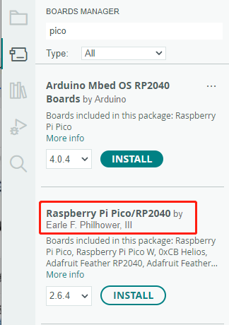
Click on Tools -> Dev Board -> Dev Board Manager -> Search for pico, it shows installed since my computer has already installed it.


Upload Demo At the First Time
-
Press and hold the BOOTSET button on the Pico board, connect the Pico to the USB port of the computer via the Micro USB cable, and release the button when the computer recognizes a removable hard drive (RPI-RP2).

- Download the demo, open arduino\PWM\D1-LED path under the D1-LED.ino.
-
Click Tools -> Port, remember the existing COM, do not need to click this COM (different computers show different COM, remember the existing COM on your computer).

-
Connect the driver board to the computer with a USB cable, then click Tools -> Ports, select uf2 Board for the first connection, and after the upload is complete, connecting again will result in an additional COM port.

-
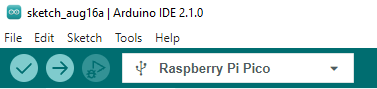
Click Tool -> Dev Board -> Raspberry Pi Pico/RP2040 -> Raspberry Pi Pico.

-
After setting, click the right arrow to upload.
- If you encounter problems during the period, you need to reinstall or replace the Arduino IDE version, uninstall the Arduino IDE needs to be uninstalled cleanly, after uninstalling the software you need to manually delete all the contents of the folder C:\Users\[name]\AppData\Local\Arduino15 (you need to show the hidden files in order to see it) and then reinstall.


Open Source Demo
- MicroPython Demo (GitHub)
- MicroPython Firmware/Blink Demo (C)
- Official Raspberry Pi C/C++ Demo
- Official Raspberry Pi MicroPython Demo
- Arduino Official C/C++ Demo
Support
If you require technical support, please go to the Support page and open a ticket.