
Difference between revisions of "PN532 NFC HAT"
| Line 480: | Line 480: | ||
'''The card provided can be unlock by "back door" leaved, however, if you use common Mifare card, once you write wrong data to Access Bits, the card will be locked and unable to restore. Be careful when you writing card''' | '''The card provided can be unlock by "back door" leaved, however, if you use common Mifare card, once you write wrong data to Access Bits, the card will be locked and unable to restore. Be careful when you writing card''' | ||
| − | === | + | ===Read/Write Mifare Classic=== |
{|border="1px" width ="800px" | {|border="1px" width ="800px" | ||
|-align="center" style="background:grey; color:white" | |-align="center" style="background:grey; color:white" | ||
| − | |''' | + | |'''Examples'''||'''Hardware Platform''' |
|-align="center" | |-align="center" | ||
|example_rw_mifare.py||Raspberry Pi | |example_rw_mifare.py||Raspberry Pi | ||
| Line 495: | Line 495: | ||
| − | + | Expected result: Close Mifare Classic card to PN532 NFC HAT, block 6 will be written with data 00 01 02 03 04 05 06 07 08 09 0A 0B 0C 0D 0E 0F. | |
| − | + | Note: | |
| − | * | + | *Before you write the block 6, you should make sure that the cipher of block 6 is 0xFF FF FF FF FF FF, which are the first six bytes of block 7. |
| − | * | + | *If you want to modify examples and try to write block N+3, you much be careful and remember the cipher. Because that N+3 is cipher block, once you forget the cipher, you should not access block N~N+2 any more. |
| − | === | + | ===Read NTAG2XX card === |
{|border="1px" width ="800px" | {|border="1px" width ="800px" | ||
|-align="center" style="background:grey; color:white" | |-align="center" style="background:grey; color:white" | ||
| − | |''' | + | |'''Examples'''||'''Hardware plaftform''' |
|-align="center" | |-align="center" | ||
|example_dump_ntag2.py||Raspberry Pi | |example_dump_ntag2.py||Raspberry Pi | ||
| Line 514: | Line 514: | ||
|} | |} | ||
| − | + | Expected result: Close Ntag215 card to PN532 NFC HAT, data of the card will be printed | |
<source lang="c"> | <source lang="c"> | ||
| Line 529: | Line 529: | ||
</source> | </source> | ||
| − | + | Note: | |
| − | *Ntag215 | + | *Ntag215 card should be purchase separately. |
| − | * | + | *Page of Ntag215 card just like blocks of Mifare card. |
| − | * | + | *The first three bytes of page 0 is UID0~UID2 of Ntag215 card, the fourth byte is parity bits, it is checksum of the first three bytes and 0x88 (Cascade Tag). |
| − | * | + | *Page 1 are UID3 ~ UID6 of card. |
| − | * | + | *The first byte of Page 2 is parity bit, it is checksum (Xor) of UID3 ~ UOD6. |
| − | === | + | ===Read/Write NTAG2XX Card=== |
{|border="1px" width ="800px" | {|border="1px" width ="800px" | ||
|-align="center" style="background:grey; color:white" | |-align="center" style="background:grey; color:white" | ||
| − | |''' | + | |'''Examples'''||'''Hardware platform''' |
|-align="center" | |-align="center" | ||
|example_rw_ntag2.py||Raspberry Pi | |example_rw_ntag2.py||Raspberry Pi | ||
Revision as of 11:14, 12 August 2019
| ||

Instruction
This is a Raspberry Pi NFC HAT based on PN532 operating in the 13.56MHz frequency range. It supports three communication interfaces: I2C, SPI, and UART.
NFC (Near Field Communication) is a wireless technology allows contactless point-to-point data communication between devices within a short distance of 10 cm. It is widely used in applications such as access control system, smart tickets, meal card, etc.
Based on the popular NFC controller PN532 with multi interface options, this HAT will easily enable NFC function for your Raspberry Pi.
Features
- Standard Raspberry Pi 40PIN GPIO extension header, supports Raspberry Pi series boards
- Onboard PN532 chip, supports various NFC/RFID cards like MIFARE/NTAG2xx, etc.
- Three interface options: I2C, SPI, and UART, configured via jumpers and switches
- Breakout control pins, for easily connecting with host boards like STM32/Arduino
- Comes with development resources and manual (examples for Raspberry Python/C, STM32, Arduino)
Note
- This module can only be used to write/read NFC card whose password is known, it cannot be used for decrypting encrypted NFC card. For example, the default password of all blocks of Mifare Classic card is 0xFFFFFFFFFFFF. the Mifare card can be written/read only when the default password isn't changed
- This module cannot be used to copy card, unless that the card use default password.
- This module cannot be used to simulate NFC card. Because ID of NFC card are 4 bytes, because of security policy of PN532, it will set the first byte of simulate card to 0x08. For more details, please refer to http://www.nfc-tools.org/index.php?title=PN53x%E3%80%82
Quick testing
You can quick test the module by connecting it to PC with USB to TTL module instead of Raspberry Pi
- 1. Hardware connection
| PN532 NFC HAT | USB to TTL Module |
|---|---|
| 3V3 | 3.3V |
| GND | GND |
| TX | RX |
| RX | TX |
- 2. Set L0 to L and L1 to L by jumpers
- 3. Connect USB to TTL Module to PC by USB cable
- 4. Open Serial assistant software, set it
- 波特率(Baud rate):115200
- 数据位(Data bits):8
- 停止位(Stop bits):1
- 校验位(Parity):None
- 流控制(Flow control):None
- 5. Check "HEX发送” and “HEX显示”
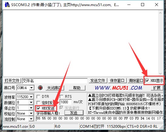

- 6. Select correct serial port and open
- 7. Send data below to wake up FN532 module:
55 55 00 00 00 00 00 00 00 00 00 00 00 00 00 00 FF 03 FD D4 14 01 17 00
(Please refer to PN532 User Manual HSU wake up condition Chapter)
The response from PN532 module should be:
00 00 FF 00 FF 00 00 00 FF 02 FE D5 15 16 00
- 8. Send data below to scan Mifare Classic card(The blue card provided, hereafter called as "card")
00 00 FF 04 FC D4 4A 01 00 E1 00
Closing card to coil part of module, module scan it and response:
00 00 FF 0C F4 D5 4B 01 01 00 04 08 04 XXXXXXXXXX 00
XXXXXXXXXX in response data is ID (3 bytes) and checksum (1 byte) of card.(Please refer to PN532 User Manual InListPassiveTarget Chapter)
Using demo codes
PN532 NFC HAT supports UART, I2C and SPI interface. You can use them according to your situation.After connecting PN532 NFC HAT (hereafter called as PN532) to Raspberry PI, then set the L1, L0 jumpers and DIP switch for different interfaces.
Choose the interface:
- UART:By default, UART interface of Raspberry Pi is used for Sheell debugging. If you use serial port for degbugging, you need to add an USB to TTL module for communicating just like what we do on #Quick testing. In this case, the serial port is mapped as ttyUSB0 instead of ttyS0
- I2C: Raspberry Pi doesn't supports I2C Clock Stretching. However, PN532 may use Clock Stretching (slaver pull-down SCL pin of I2C interface). Clock Stretching cause that Raspberry Pi cannot control all I2C devices, therefore, if you need to connect other i2C device, we do not recommend you to use I2C interface.
- SPI:We use D4 (BCM) pin as Chip select pin of SPI interface. Take care about GPIO conflict.
Raspberry Pi examples
Download demo code from #Resources, unzip and copy raspberrypi folder to /home/pi of Raspberry Pi. You can firstly copy it to /boot of SD card, then copy it to /home/pi.
- SPI Interface
1. Set L0 toL and L1 to H by jumpers
2. Connect RSTPDN->D20 by jumper
3. Set DIP switch to
| SCK | MISO | MOSI | NSS | SCL | SDA | RX | TX |
| ON | ON | ON | ON | OFF | OFF | OFF | OFF |

4. Connect PN532 NFC HAT to Raspberry Pi
| PN532 NFC HAT | Raspberry Pi (BCM) |
|---|---|
| SCK | SCK |
| MISO | MISO |
| MOSI | MOSI |
| NSS | P4 (D4) |
5. Enable SPI interface
Open Terminal of Raspberry Pi,use command: sudo raspi-config
Choose Interfacing Options -> SPI -> Yes
6. Run demo codes(Use example_get_uid.py and rpi_get_uid.c as example)
Open Terminal, navigate to directory of demo codes
cd ~/raspberrypi/
1) python code:
Enter directory of python codes: cd ~/raspberrypi/python/
Modify example_get_uid.py file,set the initialize code as :
pn532 = PN532_SPI(debug=False, reset=20, cs=4)
#pn532 = PN532_I2C(debug=False, reset=20, req=16)
#pn532 = PN532_UART(debug=False, reset=20)
Save after modifying, then run the codes with command:
python3 example_get_uid.py
2) C codes:
Enter directory of c code: cd ~/raspberrypi/c/example/
Modify rpi_get_uid.c file, set initialize code as:
PN532_SPI_Init(&pn532);
//PN532_I2C_Init(&pn532);
//PN532_UART_Init(&pn532);
Save and compile:sudo make
Run the code:
./rpi_get_uid.exe
7. Expected result:Close card to coil part of PN532, the UID of card is read
- UART interface
1. Set L0 to L and L1 to L by jumpers
2. Connecting RSTPDN ->D20 by jumper
3. Set DIP switch to
| SCK | MISO | MOSI | NSS | SCL | SDA | RX | TX |
| OFF | OFF | OFF | OFF | OFF | OFF | ON | ON |

4. Connect PN532 to Raspberry Pi
| PN532 NFC HAT | Raspberry Pi |
|---|---|
| RX | TX |
| TX | RX |
5. Enable Serial port. By default, serial port is used for Shell debugging.
Open Terminal of Raspberry PI and run command: sudo raspi-config
Choose Interfacing Options-> Serial -> No -> Yes
【Note】You need to restart Raspberry Pi after enabling serial port
6. Run demo codes(Use example_get_uid.py and rpi_get_uid.c as examples)
Open Terminal and navigate to directory of demo codes:
cd ~/raspberrypi/
1) python code:
Enter directory of python code: cd ~/raspberrypi/python/
Modify example_get_uid.py file, set initialize code to:
#pn532 = PN532_SPI(debug=False, reset=20, cs=4)
#pn532 = PN532_I2C(debug=False, reset=20, req=16)
pn532 = PN532_UART(debug=False, reset=20)
Save.Then run code by command:
python3 example_get_uid.py
2) C code:
Enter directory of c code:cd ~/raspberrypi/c/example/
Modify rpi_get_uid.c file, set initialize code to:
//PN532_SPI_Init(&pn532);
//PN532_I2C_Init(&pn532);
PN532_UART_Init(&pn532);
Save then compile code: sudo make
Run code:
./rpi_get_uid.exe
7. Expected result:Close card to coil part of PN532, the UID of card is read
- If demo code of UART run failed, you can test serial port by this example
cd ~/raspberrypi/python/
python3 example_uart_hex.py
Enter data and sent, data sent and received should be printed on terminal as expected. e.g. sent data below to wake up PN532:
55 55 00 00 00 00 00 00 00 00 00 00 00 00 00 00 FF 03 FD D4 14 01 17 00
The response data should be:
00 00 FF 00 FF 00 00 00 FF 02 FE D5 15 16 00
- I2C interface
1. Set K0 as H, L1 as L by jumpers
2. Connect RSTPDN ->D20 and INT0 -> D16(avoid from Clock Stretching) by jumpers
3. Set DIP switch to
| SCK | MISO | MOSI | NSS | SCL | SDA | RX | TX |
| OFF | OFF | OFF | OFF | ON | ON | OFF | OFF |
4. Connect PN532 to Raspberry Pi
| PN532 NFC HAT | Raspberry Pi |
|---|---|
| SCL | SCL |
| SDA | SDA |
5. Enable I2C interface
Open Terminal of Raspberry Pi and run command: sudo raspi-config
Choose Interfacing Options-> I2C -> Yes
6. Run code(Use example_get_uid.py and rpi_get_uid.c as examples)
Open ternimal and navigate to directory of demo codes:
cd ~/raspberrypi/
1) python code:
Enter directory of python code: cd ~/raspberrypi/python/
Modify example_get_uid.py file, set initialize code to:
#pn532 = PN532_SPI(debug=False, reset=20, cs=4)
pn532 = PN532_I2C(debug=False, reset=20, req=16)
#pn532 = PN532_UART(debug=False, reset=20)
Save, then run code
python3 example_get_uid.py
2) C code:
Enter directory of c code:cd ~/raspberrypi/c/example/
Modify rpi_get_uid.c file, set initialize code to:
//PN532_SPI_Init(&pn532);
PN532_I2C_Init(&pn532);
//PN532_UART_Init(&pn532);
Save then compile codes:sudo make
Run code:
./rpi_get_uid.exe
7. Expected result:Close card to coil part of PN532, the UID of card is read
Arduino examples
1. Make sure that you have installed Arduino IDE in your PC
2. Create a new folder in ...\Arduino\libraries (Installation directory of Arduino IDE) and named it as pn532
3. Copy files pn532.c, pn532.h, pn532_uno.cpp and pn532_uno.h to ...\Arduino\libraries\pn532 from Arduino demo codes
4. Demo codes is under examples\arduino (demo codes you download) directory
5. Herein we take Arduino UNO board as example
- SPI interface
1. Set L0 to L and L1 to H by hy jumpers
2. Set DIP switch to:
| SCK | MISO | MOSI | NSS | SCL | SDA | RX | TX |
| ON | ON | ON | ON | OFF | OFF | OFF | OFF |
3. Connect PN532 NFC HAT to Arduino UNO:
| PN532 NFC HAT | Arduino UNO |
|---|---|
| SCK | D13 |
| MISO | D12 |
| MOSI | D11 |
| NSS | D4 |

4. Run codes(Use examples\arduino\uno_get_uid\ uno_get_uid.ino as examples):
Open uno_get_uid.ino file, set initialize code to:
PN532_SPI_Init(&pn532);
//PN532_I2C_Init(&pn532);
Compile and upload codes to Arduino UNO
Open Serial monitor, press Reset button of Arduino Uno to reset
5. Expected result: close card to coil part of PN532, the UID of card is read and printed.
- I2C interface
1. Set L0 to L and L1 to H by jumpers
2. Set DIP switch to
| SCK | MISO | MOSI | NSS | SCL | SDA | RX | TX |
| OFF | OFF | OFF | OFF | ON | ON | OFF | OFF |
3. Connect PN532 NFC HAT to Arduino UNO
| PN532 NFC HAT | Arduino UNO |
|---|---|
| SCL | A5 |
| SDA | A4 |

4. Run code(Use examples\arduino\uno_get_uid\ uno_get_uid.ino as example):
Open uno_get_uid.ino file, set initialize code to:
//PN532_SPI_Init(&pn532);
PN532_I2C_Init(&pn532);
Compile and upload codes to Arduino UNO board
Open Serial monitor, press Reset button of Arduino UNO board to reset.
5. Expected result: close card to coil part of PN532, the UID of card is read and printed.
STM32 example
The development board used here is Open103C which is based on STM32F103CBT6.
- Download project
1. Open project by keil software(...\MDK-ARM\pn532_stm32.uvprojx),Click Rebuild to compile project.
2. Choose programmer:Options for Target -> Debug-> Use,default: ST-Link Debugger。
3. Choose download method:Options for Target -> Debug选项卡 -> Settings -> Debug -> Port,Default: JTAG.
4. Connect Open board to PC by programmer. Note that you should power Open board separately.
5. Click Download to download project.
- Hardware connection
1. Set L0 to L and L1 to H by jumpers
2. Set DIP switch to
| SCK | MISO | MOSI | NSS | SCL | SDA | RX | TX |
| ON | ON | ON | ON | OFF | OFF | OFF | OFF |
3. Connect PN632 to Open103C board
| PN532 NFC HAT | STM32F103CBT6 |
|---|---|
| SCK | PA5 |
| MISO | PA6 |
| MOSI | PA7 |
| NSS | PA4 |
4. Connect USB to TTL module to UART1 interface (PA9->RX, PA10->TX) of STM32 and PC.
5. Open serial assistant software, and reset Open103C
6. Expected result: close card to coil part of PN532, the UID of card is read and printed.
Description of examples
Examples above are used to read UID of Mifare Classic card (example_get_uid.py / rpi_get_uid.exe / uno_get_uid.ino / stm32_get_uid), here we describe other examples.
【Note】
Before run the examples, you should set the L0/L1 pins and DIp switch according to interfaces used. You cannot set all the pins to ON,it will cause that data received are wrong. Here we take 0 is OFF and 1 is ON
- UART interface:Set jumpers [L1..L0] as LL,set DIP switch to 00000011
- I2C interface: Set jumpers [L1..L0] as LH, set DIP switch to 00001100.
- SPI interface: Set jumpers [L1..L0] as HL, set DIP switch to 11110000.
Read Mifare Classic card
| Examples | Hardware platform |
| example_dump_mifare.py | Raspberry Pi |
| rpi_dump_mifare.c | Raspberry Pi |
| uno_dump_mifare.ino | Arduino UNO |
| stm32_dump_mifare/MDK-ARM/pn532_stm32.uvprojx | STM32F103CBT6 |
Expected result:Close the Mifare Classic card to PN532 NFC HAT, the data in card are printed:
0 : 37 F9 20 69 87 08 04 00 62 63 64 65 66 67 68 69
1 : 00 00 00 00 00 00 00 00 00 00 00 00 00 00 00 00
2 : 00 00 00 00 00 00 00 00 00 00 00 00 00 00 00 00
3 : 00 00 00 00 00 00 FF 07 80 69 FF FF FF FF FF FF
4 : 00 00 00 00 00 00 00 00 00 00 00 00 00 00 00 00
5 : 00 00 00 00 00 00 00 00 00 00 00 00 00 00 00 00
6 : 00 00 00 00 00 00 00 00 00 00 00 00 00 00 00 00
7 : 00 00 00 00 00 00 FF 07 80 69 FF FF FF FF FF FF
8 : 00 00 00 00 00 00 00 00 00 00 00 00 00 00 00 00
9 : 00 00 00 00 00 00 00 00 00 00 00 00 00 00 00 00
10 : 00 00 00 00 00 00 00 00 00 00 00 00 00 00 00 00
11 : 00 00 00 00 00 00 FF 07 80 69 FF FF FF FF FF FF
… …
63 : 00 00 00 00 00 00 FF 07 80 69 FF FF FF FF FF FF
Note:
- Data of every row are related to every block of card
- First 4 bytes of block 0 are UID of Mifare Classic card, fifth byte is parity bit. It is checksum of the first 4 bytes.
- Block 0 (UID) of classic card cannot be modified.
- Every sector have four blocks, these four blocks use same password. For example, blocks 4N~4N+3 belong to same sector.
- Block 4N+3 is cipher block, that is if you want to read the data of blocks 4N~4N+2, you must use cipher of block 4N+3.
- The car has 64 blocks in total, which is 1K.
e.g. To read block 6, we need to use cipher of the related sector, that is the data of block 7.
7 : 00 00 00 00 00 00 FF 07 80 69 FF FF FF FF FF FF
The first six bytes are KEY A, it is default FF FF FF FF FF FF, if you read it, the data response would be 00 00 00 00 00 00. The last six bytes are KEY B saved in plaintext. KEY A and KEY B of Mifare Classic card are default FF FF FF FF FF FF.
Four bytes in the middle are Access Bits, default FF 07 80 69. Access Bits are used for controlling access permission, it will be locked if user write wrong data to them.

For example, if you write 0xFF to byte 6, high four bits of byte 7 should be 0b0000,low four bits of byte 8 should be 0b0000. For more details, please refer to Access conditions for data blocks section of MF1S50YYX_V1.pdf
The card provided can be unlock by "back door" leaved, however, if you use common Mifare card, once you write wrong data to Access Bits, the card will be locked and unable to restore. Be careful when you writing card
Read/Write Mifare Classic
| Examples | Hardware Platform |
| example_rw_mifare.py | Raspberry Pi |
| rpi_rw_mifare.c | Raspberry Pi |
| uno_rw_mifare.ino | Arduino UNO |
| stm32_rw_mifare/MDK-ARM/pn532_stm32.uvprojx | STM32F103CBT6 |
Expected result: Close Mifare Classic card to PN532 NFC HAT, block 6 will be written with data 00 01 02 03 04 05 06 07 08 09 0A 0B 0C 0D 0E 0F.
Note:
- Before you write the block 6, you should make sure that the cipher of block 6 is 0xFF FF FF FF FF FF, which are the first six bytes of block 7.
- If you want to modify examples and try to write block N+3, you much be careful and remember the cipher. Because that N+3 is cipher block, once you forget the cipher, you should not access block N~N+2 any more.
Read NTAG2XX card
| Examples | Hardware plaftform |
| example_dump_ntag2.py | Raspberry Pi |
| rpi_dump_ntag2.c | Raspberry Pi |
| uno_dump_ntag2.ino | Arduino UNO |
| stm32_dump_ntag2/MDK-ARM/pn532_stm32.uvprojx | STM32F103CBT6 |
Expected result: Close Ntag215 card to PN532 NFC HAT, data of the card will be printed
0: 04 85 32 3b
1: 92 a8 64 80
2: de 48 00 00
3: e1 10 3e 00
4: 03 00 fe 00
5: 00 00 00 00
6: 00 00 00 00
7: 00 00 00 00
… …
134: 00 00 00 00
Note:
- Ntag215 card should be purchase separately.
- Page of Ntag215 card just like blocks of Mifare card.
- The first three bytes of page 0 is UID0~UID2 of Ntag215 card, the fourth byte is parity bits, it is checksum of the first three bytes and 0x88 (Cascade Tag).
- Page 1 are UID3 ~ UID6 of card.
- The first byte of Page 2 is parity bit, it is checksum (Xor) of UID3 ~ UOD6.
Read/Write NTAG2XX Card
| Examples | Hardware platform |
| example_rw_ntag2.py | Raspberry Pi |
| rpi_rw_ntag2.c | Raspberry Pi |
| uno_rw_ntag2.ino | Arduino UNO |
| stm32_rw_ntag2/MDK-ARM/pn532_stm32.uvprojx | STM32F103CBT6 |
预期结果:把NTAG215卡贴近PN532 NFC HAT,第6块的内容会被改写成00 01 02 03。
说明:
- 第2页的最后两个字节用于标记并锁定03h到0Fh的对应的页为只读,并且这个操作不可逆。使用的时候应该注意这个情况。见NTAG213/215/216 的Static lock bytes (NTAG21x) 节。

- 要锁定第10h页之后的数据,则把对应的地址写入28h页(NTAG213)或82h页(NTAG215)或E2h页(NTAG216)的前3字节,第4字节读取结果永远是0xBD。见NTAG213/215/216 的Dynamic Lock Bytes节

- Ntag2xx卡的功能详情请参见 NTAG213/215/216 手册的相关内容。
设置PN532的GPIO电平
| 程序 | 开发板 |
| example_write_gpio.py | Raspberry Pi |
| rpi_write_gpio.c | Raspberry Pi |
| uno_write_gpio.ino | Arduino UNO |
| stm32_write_gpio/MDK-ARM/pn532_stm32.uvprojx | STM32F103CBT6 |
预期结果:打印PN532的GPIO电平
Pin P30: 1
Pin P31: 0
Pin P32: 1
Pin P33: 0
Pin P34: 1
Pin P35: 0
Pin P71: 0
Pin P72: 1
Pin I0: 1
Pin I1: 0
说明:
程序尝试设置管脚电平:P30 -> 高,P31 -> 低,P33 -> 低,P35 -> 低,P71 -> 低,P72 -> 高
注意:
- P32是 int0,一旦写入低电平,将会导致模块复位。
- P34是SIC_CLK,读取的结果是高电平。
- P71是MISO,在SPI模式下,读取的结果是高电平。
- P72是SCK,在SPI模式下,读取的结果是高电平。
- 模块上电的时候, PN532 会根据I0/I1的电平设置通讯接口。之后可以移除跳线帽,作为普通的GPIO使用。
PN532的P30 – P35电平会在硬件复位(RSTPDN置低2ms然后置高)之后,恢复为高电平。
读取PN532的GPIO电平
| 程序 | 开发板 |
| example_read_gpio.py | Raspberry Pi |
| rpi_read_gpio.c | Raspberry Pi |
| uno_read_gpio.ino | Arduino UNO |
| stm32_read_gpio/MDK-ARM/pn532_stm32.uvprojx | STM32F103CBT6 |
预期结果:会打印PN532的GPIO电平
Port P3: 0x3f
Port P7: 0x07
Port I: 0x07
Pin P30: 1
Pin P31: 1
Pin P32: 1
Pin P33: 1
Pin P34: 1
Pin P35: 1
Pin I0: 1
Pin I1: 0
说明:
- PN532的P30 – P35电平会在硬件复位(RSTPDN置低2ms然后置高)之后,恢复为高电平。
Resources
FAQ
Supports
Support
If you require technical support, please go to the Support page and open a ticket.