
Difference between revisions of "Open103R"
m (Text replace - "*Design Resources" to " ==Cortex M3 Guide== *Cortex-M3 Technical Reference Manual *Cortex-M3 Definitive Guide ==UCOS Source) |
|||
| Line 22: | Line 22: | ||
Open103R is a STM32 development board designed for STM32F103R series, features the STM32F103RCT6 MCU, and integrates various standard interfaces, pretty easy for peripheral expansions. | Open103R is a STM32 development board designed for STM32F103R series, features the STM32F103RCT6 MCU, and integrates various standard interfaces, pretty easy for peripheral expansions. | ||
| − | + | {{Open103R User Manual}} | |
{{Resource list| | {{Resource list| | ||
*[http://www.waveshare.com/Open103R-Standard.htm Introduction] | *[http://www.waveshare.com/Open103R-Standard.htm Introduction] | ||
Revision as of 06:57, 14 August 2015
| ||
| ||
| ||
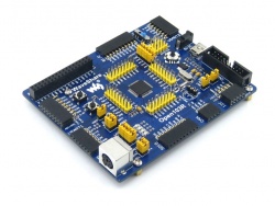


Open103R is a STM32 development board that features a STM32F103RCT6 device as the microcontroller. There are further expansions with various optional accessory boards for specific application. The modular and open design makes it the ideal for starting application development with STM32F family.
Open103R is a STM32 development board designed for STM32F103R series, features the STM32F103RCT6 MCU, and integrates various standard interfaces, pretty easy for peripheral expansions.
Getting Started with modules
We provide various modules for Open103R development board aiming to improve your development efficiency. These modules are not only designed for STM32 but also can be used for many other MCU platforms. Let's begin with the demos.
Development Environment
- KEIL MDK Version: 4.54 or above
- Programmer/Debugger: ULINK/V2 or ST-Link
- Programming/Debugging interface: JTAG/SWD
- Serial port communication settings:
| Select a proper COM port | |
|---|---|
| Baud rate | 115200 |
| Data bits | 8 |
| Stop bits | 1 |
| Parity bits | None |
| Flow control | None |
5IOs
Overview
5I/Os demo, detect the 8 independent button is pressed or not.
Hardware connection

- Connect the "5IO Keypad" to the onboard 8I/Os interface (make sure the G pin on the module connects to the GND pin on the 8I/Os)
- Connect a serial port converter(RS232) to the onboard USART1 interface
Operation and result
The below information will be printed on the serial debugging assistant:

8IOs
Overview
8I/Os demo, detect the 8 independent button is pressed or not
Hardware connection

- Connect the "8 Push Button" to the onboard 8I/Os interface (make sure the G pin on the module connects to the GND pin on the 8I/Os)
Operation and result
Push the button, the LED will keep changing accordingly.

ADC+DMA
Overview
AD acquisition demo, output via DMA channel
Hardware connection

Connect the Analog Test Board to the board via SPI1 (ADC+DAC) interface
Operation and result
- Rotate the potentiometer on the Analog Test Board, the below information will be printed on the serial debugging assistant:

CAN-LoopBack
Overview
Internal CAN signal demo
Operation and result
- LED keep blinking;
- The below information will be printed on the serial debugging assistant:

CAN-Normal
Overview
CAN communication between two boards
Hardware connection
- Two "SN65HVD230 CAN Board" are required, connect them to two Open103R boards respectively
- Connect the two CAN boards via DuPont wire(CANL<->CANL, CANH<->CANH)
Operation and result
- The below information will be printed on the serial debugging assistant:

DAC
Overview
DA output demo, output via DMA channel
Hardware connection

- Connect the Analog Test Board to the board via SPI1(ADC+DAC)interface
- Connect the 5V pin headers on both the main board and the Analog Test Board via jumper wire
Operation and result
- You should hear sound from the Analog Test Board
ENC28J60
Overview
The development board communicates with the PC via Internet
Hardware connection

- Connect the ENC28J60 Ethernet Board to the board via SPI1(ADC+DAC)interface
- The IP of the PC configuring as 192.168.0.xxx;for example:
- Configuring IP of both the PC and the module on the same network:
- Right click the Internet -> Properties -> ClickLocal connection->ClickProperties->Find Internet Protocol Version4(TCP/IP V4, the following dialog box will pop up, set the appropriate IP address, subnet mask, and default gateway:
- IP address: 192.168.0.11
- Subnet Mask: 255.255.255.0
- Default Gateway: 192.168.0.1
- Configuring IP of both the PC and the module on the same network:
Operation and result
Open the browser; enter 192.168.0.100/888; press the Enter key:

GPIO LED JOYSTICK
Overview
Change LED status via button, joystick
Hardware connection
Short the LED JMP,JOYSTICK JMP
Operation and result
Push the button or joystick, the LED status should keep changing accordingly
I2C
Overview
Read and write data on E2PROM via I2C protocol
Hardware connection

- Connect a serial port converter to the onboard USART1 interface
- Connect the AT24/FM24 Board to the board via I2CX interface( connect to I2C1 or I2C2 depends on the program)
Operation and result
- The below information will be printed on the serial debugging assistant:

LCD
Overview
Control the LCD via FSMC
Hardware connection

- Connect the 3.2inch 320x240 Touch LCD (C) to the board
Operation and result
- Display image on the LCD:

NRF24L01
Overview
NRF24L01 transmits data via wireless way.
Hardware connection

- Connect a serial port converter to the onboard USART1 interface
- Connect the NRF24L01 Board to the board via SPI interface
- Software configuration
- Two NRF24L01 are needed for this demo, the software configuring as below:
- When configuring as mode of transmitting, enabled: #define T_O_R 1, comment out: //#define T_O_R 0;
- When configuring as mode of receiving, enable: #define T_O_R 0, comment out: //#define T_O_R 0
Operation and result
Message will be printed on the serial debugging assistant.
One-Wire
Overview
Connect the DS18B20, detect the temperature
Hardware connection
- Connect a serial port converter to the onboard USART1 interface
- Connect the DS18B20 to the onboard One-wire socket.
Operation and result
The below information will be printed on the serial debugging assistant:

PS2
Overview
Drive PS2 keyboard via 2 GPIO
Hardware connection

- Connect a serial port converter to the onboard USART1 interface
- Connect the PS2 keyboard to the board via PS2 interface
- Short the PS2 JMP.
Operation and result
The below key values will be printed on the serial debugging assistant while pressing the PS2 keyboard:

RTC
Overview
Open103R onboard RTC demo
Operation and result
The below information will be printed on the serial debugging assistant:

SD_FatFS
Overview
Read and write SD card, SD card is FAT file system.
Hardware connection

- Connect a serial port converter to the onboard USART1 interface
- Connect the Micro SD Storage Board (with SD card) to the board via SPI1 interface
Operation and result
Message will be printed on the serial debugging assistant.
SDIO
Overview
Read and write information in SD card
Hardware connection
- Connect a serial port converter to the onboard USART1 interface
- Connect the Micro SD Storage Board (with SD card) to the board via SPI1 interface
Operation and result
The below information will be printed on the serial debugging assistant:

SPI
Overview
Drive the AT45DBXX DataFlash Board via SPI interface
Hardware connection

- Connect the AT45DBXX DataFlash Board to the board via SPI2 interface
Operation and result
The below information will be printed on the serial debugging assistant:

TouchPanel
Overview
Control LCD via FSMC; display the touch screen function of the LCD
Hardware connection
- Connect the 3.2inch 320x240 Touch LCD (C) to the board
Operation and result
Calibrate the LCD first, then touch it, draw any line on it.
uCOSII2.91+UCGUI3.90A
Overview
UcosII+GUI demo
Hardware connection
- Connect the 3.2inch 320x240 Touch LCD (C) to the board
Operation and result
- Display image on the LCD

USART
Overview
USART serial port communication demo
Hardware connection
Operation and result
The below information will be printed on the serial debugging assistant:

USB-JoyStick Mouse
Overview
USB mouse demo, the development board works as USB device to control the computer
Hardware connection
- Connect the board to the computer via USB cable
- Software connection
Operation and result
An USB device will appear on the PC device manager: Control the computer cursor by joystick
VS1003B
Overview
Play music via VS1003B
Hardware connection

- Connect the "VS1003B MP3 Board" to the onboard SPI1 interface
Operation and result
- VS1003 (GPIO): P0 LED keep blinking
- VS1003 (line in): can hear music from the PC
- VS1003 (line out): can hear music from the MCU FLASH
- VS1003 (record): can hear sound from the microphone
FAQ
Support
Support
If you require technical support, please go to the Support page and open a ticket.