JetRacer ROS AI Kit Tutorial I: Assembly Manual
JetRacer AI Assembly Steps
Install Motors and Rear Wheels
1. Fix the motor on the metal chassis. Pay attention to the screws we use are M3*6. If you use the wrong screws, the motor will not rotate normally.

2. Fix the coupler screws on the coupler by the spanner.

3. Install the coupler on the motor shaft and lock the screws. (Note that the coupler screws should be locked on the shaft side.)

4. Install the tires on the coupler with PM4*8.

5. Install the servo bracket on the metal chassis.

Servo Middle Position and Installation
1. Install the battery on the expansion board, connect the charger and activate the battery protection.


2. Turn on the power switch after activating the battery successfully. The LED on the board will be flashing.

3. Connect the servo to the expansion board, and the servo will rotate to 90 degrees, that is, the middle position. Note: the servo cable order is: Yellow-PWM, Red-5V, Brown-GND

4. Fix the servo in the bracket with M3*8 screws and M3 nut, and pay attention to the servo direction.
Install Servo Wheel and Connecting Rod
1. Fix M3*22 standoffs with PM3*8.

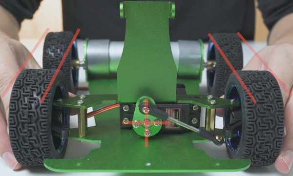
2. Install the metal servo wheel on the servo, make sure that the holes of the servo wheel appear as a cross, and then install. If there is no cross, you can slowly rotate the servo wheel until a cross appears and then install it.

3. Fix the servo wheel fixing panel to the metal servo wheel with the included screws.

4. Use two M3 ball joints (small) and a short rod to form the pull bar of the servo. Use two M3 ball joints (big) and a long rod to form the pull bar of the front wheel. The two ball heads are horizontal.

5. Use KM2.5*12 screws and M2 self-lock nuts to fix the flat end of the pull bar on the servo.

6. Install the camera bracket on the M3*22 standoffs by PM3*8.

7. Install the large and small bearings in the steering knuckle.

8. Lock the wheel on the steering knuckle with KM4*20 screws and M4 self-lock nuts. Be careful not to lock it too loosely here to avoid shaking the front wheel of the car, and also not to lock it too tightly so that the front wheel cannot rotate normally. After the installation is completed, turn the wheel to test whether it can rotate smoothly.

9. Use PM2*30 screws and M2 self-lock nuts to install the front wheel on the JetRacer. Be careful not to lock it too tightly. After the installation is complete, turn it left and right to test whether it turns smoothly.
10. Adjust the length of the servo pull bar so that when the servo is 90 degrees, the tires will not deflect towards the front.
