
IMX462 2MP Starlight Camera
| ||
| ||

Overview
Introduction
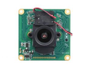
Onboard 1/2.8 inch Sony starlight camera sensor, IMX462 2MP Starlight Camera adopts back-illuminated pixel technology, which can realize high-quality imaging in visible light and near-infrared band. Onboard IR-CUT, IXM462 2MP Starlight Camera can be switched to day or night mode freely with a resolution of up to 1920 x 1080. With ISP, the camera has a better imaging effect. Also, we provide 99° and 127° field of view options, you can choose according to your needs.
Specification
| IMX462-99 | IMX462-127 | |
|---|---|---|
| Image Sensor | ||
| Sensor | SONY IMX462LQR-C STARVIS | |
| Pixel | 2.07MP | |
| Resolution | 1920 × 1080 | |
| Pixel size | 2.9um × 2.9um | |
| Shutter | Rolling Shutter | |
| ISP Image Processing | ||
| Frame rate | 1080p@25fps, 1080p@30fps | |
| Exposure | AE (Auto Exposure)/Manual | |
| White Balance | AWB (Auto White Balance), Manual | |
| Shutter | 1/25 (1/30)s to 1/50,000s (support slow shutter) | |
| Noise Reduction | 2D/3D Noise Reduction | |
| Image Settings | Brightness, Contrast, Sharpness, Saturation, Adjustable GAMMA, Image Flip, Image Mirror | |
| Image Enhancement | Backlight compensation, DOL-WDR, defogging | |
| Day and Night Switch | External trigger synchronous switch, manually switch to RGB and monochrome. | |
| Lens | ||
| Field of View (FOV) | 99.1°(D) / 83.5°(H) / 44.6°(V) | 127.9°(D) / 106.9°(H) / 56.9°(V) |
| Aperture | F1.0 | F1.61 |
| Focal Length | 4.0mm | 3.18mm |
| Distortion | -33.8% | -51% |
| Focus Method | Manual | |
| Working Parameters | ||
| Operating Temperature | -10℃~60℃ | |
| Working Humidity | <=95% no condensation | |
Dimensions
PCBA Dimension

PCBA 3D Drawing
Working with Raspberry Pi
Note
As IMX462 is not the default camera for the Raspberry Pi, it can not be compatible with the libcamera or raspciam library in Raspberry Pi. Hence you need to install another driver and control script.
The driver provided only supports the Raspberry Pi OS system, and other systems are not currently supported.
Configure I2C
Open the terminal of Raspberry Pi and enter the following command:
sudo raspi-config
Choose Interface Options -> I2c -> Yes.
Download and Install Driver
Before downloading the driver, you need to make sure that the latest Raspberry Pi system has been programmed well. Connect the camera and complete the boot configuration.
Open the terminal of the Raspberry Pi and enter the following command:
wget https://github.com/veyeimaging/raspberrypi_v4l2/releases/latest/download/raspberrypi_v4l2.tgz
tar -xzvf raspberrypi_v4l2.tgz
cd raspberrypi_v4l2/release/
chmod +x *
sudo ./install_driver.sh veyecam2m
Install Driver
Raspberry Pi 5
cd ~/raspberrypi_v4l2/release/
sudo ./install_driver_rpi5.sh veyecam2m
Due to the use of the media control API in Raspberry Pi 5, it is necessary to properly set up the media graph before it can be used. This includes correctly configuring the format of the media pads and linking them properly. A series of scripts is provided in the rpi5_scripts directory to implement this functionality. Therefore, after each power-up, it is necessary to run the following command to configure it before normal operation can commence.
cd ~/raspberrypi_v4l2/rpi5_scripts/
sudo ./find_entity.sh
sudo ./media_setting_rpi5.sh veyecam2m
Other Raspberry Pi
cd ~/raspberrypi_v4l2/release/
sudo ./install_driver.sh veyecam2m
Unload the Driver (Optional)
If you want to replace it with another camera driver, you can unload the current driver:
sudo ./uninstall_driver.sh veyecam2m
Camera Test
Note: if you want to control the camera by the remote terminal, please enter the command "export DISPLAY=:0" to specify the screen to output before using the preview command.
Preview with qv4l2
- Install tool:
sudo apt-get install qv4l2
- Run it:
Open the software by typing the following in the terminal command line interface:
qv4l2
After running it, click on the play icon in the upper left corner to preview the demo.
Preview with Gstreamer
Install Gstreamer
- Open the terminal of the Raspberry Pi and enter the following commands to install:
sudo apt-get install gstreamer1.0-tools
sudo apt-get install libx264-dev libjpeg-dev
sudo apt-get install libgstreamer1.0-dev libgstreamer-plugins-base1.0-dev libgstreamer-plugins-bad1.0-dev gstreamer1.0-plugins-ugly gstreamer1.0-tools gstreamer1.0-gl gstreamer1.0-gtk3 gstreamer1.0-plugins-good gstreamer1.0-plugins-bad
Snap a Picture
gst-launch-1.0 v4l2src num-buffers=1 device=/dev/video0 ! 'video/x-raw, format=(string)UYVY, width=1920,height=1080' ! jpegenc ! filesink location=test_image.jpg
Video Preview
gst-launch-1.0 v4l2src io-mode=dmabuf device=/dev/video0 ! "video/x-raw,format=(string)UYVY, width=(int)1920, height=(int)1080,framerate=(fraction)30/1" ! v4l2convert capture-io-mode=dmabuf output-io-mode=dmabuf ! autovideosink sync=false -v
Video Preview (Add timestamp)
gst-launch-1.0 v4l2src device=/dev/video0 ! "video/x-raw,format=(string)UYVY, width=(int)1920, height=(int)1080,framerate=(fraction)30/1" ! videoconvert ! videoscale ! clockoverlay time-format="%D %H:%M:%S" ! video/x-raw, width=640, height=360 ! autovideosink sync=false -v
Video Record (mkv)
gst-launch-1.0 -e v4l2src io-mode=dmabuf device=/dev/video0 num-buffers=300 ! "video/x-raw,format=(string)UYVY, width=(int)1920, height=(int)1080,framerate=(fraction)30/1" ! v4l2h264enc capture-io-mode=dmabuf output-io-mode=dmabuf extra-controls="controls, h264_profile=4, video_bitrate=6200000" ! 'video/x-h264, profile=high, level=(string)4' ! h264parse ! matroskamux ! filesink location=output.mkv
Video Record (mp4)
gst-launch-1.0 -e v4l2src io-mode=dmabuf device=/dev/video0 num-buffers=300 ! "video/x-raw,format=(string)UYVY, width=(int)1920, height=(int)1080,framerate=(fraction)30/1" ! v4l2h264enc capture-io-mode=dmabuf output-io-mode=dmabuf extra-controls="controls, h264_profile=4, video_bitrate=6200000" ! 'video/x-h264, profile=high, level=(string)4' ! h264parse ! mp4mux ! filesink location=video.mp4
TCP Video Streaming
- In the Raspberry Pi terminal, the monitoring port is 5000.
gst-launch-1.0 -v v4l2src device=/dev/video0 num-buffers=-1 ! "video/x-raw,format=(string)UYVY, width=(int)1920, height=(int)1080,framerate=(fraction)30/1" ! v4l2h264enc extra-controls="controls, h264_profile=4, video_bitrate=4000000" ! 'video/x-h264, profile=high, level=(string)4' ! h264parse ! rtph264pay config-interval=1 pt=96 ! gdppay ! tcpserversink host=x.x.x.x port=5000
- Get from the terminal.
gst-launch-1.0 -v tcpclientsrc host=x.x.x.x port=5000 ! gdpdepay ! rtph264depay ! avdec_h264 ! autovideosink sync=false
- Note: x.x.x.x needs to be replaced according to the actual Raspberry Pi IP address, such as "gst-launch-1.0 -v tcpclientsrc host=192.168.1.10 port=5000 ! gdpdepay ! rtph264depay ! avdec_h264 ! autovideosink sync=false".
Get video with Opencv
gst-launch-1.0 v4l2src device=/dev/video0 ! "video/x-raw,format=(string)UYVY, width=(int)1920, height=(int)1080,framerate=(fraction)30/1" ! videoscale ! "video/x-raw,width=640,height=480" ! videoconvert ! "video/x-raw, format=(string)BGR" ! appsink
Note: This demo is not directly run in the Raspberry Pi but as a parameter of "video. Capture(str) str" for calling.
Compute Module
If you use Raspberry Pi CM3 or CM4, "dtb" and device tree are required.
Loading Device Tree
sudo wget https://datasheets.raspberrypi.com/cmio/dt-blob-dualcam.bin -O /boot/dt-blob.bin
sudo cp ~/raspberrypi_v4l2/release/driver_bin/$(uname -r)/veyecam2m.dtbo /boot/overlays/veyecam2m.dtbo
sudo reboot
Device Description
CM4 adopts two-channel I2C to connect two cameras respectively: i2c-0 and i2c10.
If you connect the two-channel cameras at the same time, the system will recognize them as video0 and video2.
CAM0 Preview
gst-launch-1.0 v4l2src io-mode=dmabuf device=/dev/video0 ! "video/x-raw,format=(string)UYVY, width=(int)1920, height=(int)1080,framerate=(fraction)30/1" ! v4l2convert capture-io-mode=dmabuf output-io-mode=dmabuf ! autovideosink sync=false -v
CAM1 Preview
gst-launch-1.0 v4l2src io-mode=dmabuf device=/dev/video2 ! "video/x-raw,format=(string)UYVY, width=(int)1920, height=(int)1080,framerate=(fraction)30/1" ! v4l2convert capture-io-mode=dmabuf output-io-mode=dmabuf ! autovideosink sync=false -v
Working with Jetson Nano
Version Statement
The IMX462 camera is used on the NVIDIA platform to install the relevant driver and load the new device tree file. Currently supports Jetson Nano, Jetson Xavier NX, Jetson TX2 NX, and Jetson AGX Xavier.
Note: AGX Xavier and other interfaces are packaged differently, and you need to purchase or make an adapter board support them.
Currently supported Jetapck versions:
- Jetpack4.2.2, L4T version r32.2.1
- Jetpack4.3, L4T version r32.3.1
- Jetpack4.4, L4T version r32.4.3
- Jetpack4.4.1, L4T version r32.4.4
- Jetpack4.5, L4T version r32.5
- Jetpack4.5.1, L4T version r32.5.1
- Jetpack4.6, L4T version r32.6.1
- Jetpack4.6.1, L4T version r32.7.1
- Jetpack4.6.2, L4T version r32.7.2
- Jetpack5.0.1DP, L4T version r34.1.1
Check JetPack Version
- If you are not sure whether your software version is supported, you can use the following command to check.
cat /etc/nv_tegra_release
- If it shows R32 (release), REVISION: 4.3 means the current version is R32.4.3.
Hardware Connection
- Please arrange the camera cable, with the gold finger contact surface facing the side of the core board, and connect it to the jetson development board.

- Jetpack4.x Version
To use the IMX462 camera, the Image and DTB parts of the Jetson system need to be updated. In the Image part, the camera driver is added, and the dtb part indicates the camera model used. In general, you only need to use the compiled Image and dtb, and you don't need to compile it according to the code if it is not necessary.
- JetPack 5.0 or later (for Xavier NX and AGX Xavier and higher performance modules)
The driver is no longer compiled into Image, but loaded into the system as an independent module. dtb is still compiled as a whole to facilitate replacement. dtb can also be dynamically loaded as an overlay.
BSP Package
- Download path: https://github.com/veyeimaging/nvidia_jetson_veye_bsp
- BSP package:
- Precompiled dtb for different platforms
- driver source code
- dts source code
- i2c communication toolset
- The correspondence between DTB package files and boards:
- Nano B01
- tegra210-p3448-0000-p3449-0000-b00.dtb
- AGX XAVIER
- tegra194-p2888-0001-p2822-0000.dtb
- XAVIER NX
- tegra194-p3668-all-p3509-0000.dtb
- (Jetpack5.0.1) tegra194-p3668-0000-p3509-0000.dtb
- AGX Orin
- tegra234-p3701-0000-p3737-0000.dtb
Driver Installation
Upgrade directly on the jetson board:
wget https://github.com/veyeimaging/nvidia_jetson_veye_bsp/releases/latest/download/nvidia_jetson_veye_bsp.tar.gz
tar -xzvf nvidia_jetson_veye_bsp.tar.gz
Upgrade Image (for JetPack4.x)
- Back up the original Image:
cp /boot/Image /boot/Image.backup
cp /boot/Image.sig /boot/Image.sig.backup
- (Jetson Nano) In the downloaded bsp package, find the corresponding Image compressed package, decompress it, and then execute the command.
sudo cp <path to your Image dir>/Image /boot/Image -f
Note here to replace <path to your Image dir> with the path of the Image file you unzipped.
- (NX) If you are using Xavier NX, you need to use the signed version, that is, the package with the word signed.
sudo cp <path to your Image dir>/Image /boot/Image -f
sudo cp <path to your Image dir>/Image.sig /boot/Image.sig -f
Module Installation (For JetPack5.x)
- Check Linux version:
uname -r
- Find the corresponding driver version directory in the nvidia_jetson_veye_bsp/ko directory, and run the command:
sudo cp nvidia_jetson_veye_bsp/ko/$(uname -r)/* /lib/modules/$(uname -r)/kernel/drivers/media/i2c/ -f
sudo depmod
Upgrade dtb
- In the bsp package directory, find the dtb file corresponding to the camera (VEYE-MIPI-CAM2M) model and L4T version number. Copy:
sudo mkdir /boot/veyecam/
sudo cp <path to your dtb dir>/<DTB file name> /boot/veyecam -f
- Backup the extlinux.conf file.
cp /boot/extlinux/extlinux.conf /boot/extlinux/extlinux.conf.back
- Edit the /boot/extlinux/extlinux.conf file and add the following line at the bottom:
FDT /boot/veyecam/<DTB file name>
Note: <DTB file name> should be replaced with the dtb name corresponding to the motherboard, to ensure that the file indicated by the FDT line does exist correctly.
- Reboot the system:
sudo reboot
Camera Test
Check if the camera is connected properly
- After the system upgrade is successful, you can enter the following command in the Jetson nano terminal to check whether the camera is connected normally.
dmesg | grep veye
There are prompts such as IMX462. Also, view ls /dev/ there are videox device nodes.
Test Camera (Gstreamer)
- Video preview 1080P
export DISPLAY=:0
gst-launch-1.0 nvv4l2camerasrc device=/dev/video0 ! "video/x-raw(memory:NVMM),format=(string)UYVY, width=(int)1920, height=(int)1080" ! nvvidconv ! "video/x-raw(memory:NVMM),format=(string)NV12" ! nvoverlaysink sync=false
gst-launch-1.0 nvv4l2camerasrc device=/dev/video0 ! "video/x-raw(memory:NVMM),format=(string)UYVY, width=(int)1920, height=(int)1080" ! nvvidconv ! "video/x-raw(memory:NVMM),format=(string)I420" ! nvoverlaysink sync=false
- Video preview 1080p (xvimagesink)
export DISPLAY=:0
gst-launch-1.0 -e v4l2src io-mode=4 device=/dev/video0 do-timestamp=true ! 'video/x-raw, width=1920, height=1080, framerate=30/1, format=UYVY' ! xvimagesink sync=false
- Preview two cameras at the same time
WIDTH=960
HEIGHT=540

CAPS="video/x-raw(memory:NVMM),format=(string)UYVY, width=1920, height=1080"

gst-launch-1.0 nvcompositor name=comp sink_0::xpos=0 sink_0::ypos=0 sink_0::width=$WIDTH sink_0::height=$HEIGHT sink_1::xpos=$WIDTH sink_1::ypos=0 sink_1::width=$WIDTH sink_1::height=$HEIGHT ! nvoverlaysink nvv4l2camerasrc device=/dev/video0 ! $CAPS ! nvvidconv ! "video/x-raw(memory:NVMM),format=(string)I420"! comp. nvv4l2camerasrc device=/dev/video1 ! $CAPS ! nvvidconv ! "video/x-raw(memory:NVMM),format=(string)I420"! comp
- Calling Gstreamer with Opencv
gst-launch-1.0 nvv4l2camerasrc ! video/x-raw(memory:NVMM), format=(string)UYVY, width=(int)1920, height=(int)1080 ! nvvidconv ! video/x-raw(memory:NVMM), format=(string)I420 ! nvvidconv ! video/x-raw, format=(string)BGRx ! videoconvert ! video/x-raw, format=(string)BGR ! appsink
- Video recording 1080p
gst-launch-1.0 nvv4l2camerasrc num-buffers=300 ! "video/x-raw(memory:NVMM),format=(string)UYVY, width=(int)1920, height=(int)1080" ! nvvidconv ! "video/x-raw(memory:NVMM),format=(string)NV12" ! nvv4l2h264enc control-rate=1 bitrate=10000000 ! h264parse ! qtmux ! filesink location=filename.mp4 -e
- Play video
gst-launch-1.0 filesrc location=filename.mp4 ! qtdemux ! queue ! h264parse ! nvv4l2decoder ! nvoverlaysink -e
- Snap a picture
gst-launch-1.0 v4l2src num-buffers=1 ! "video/x-raw,format=(string)UYVY, width=(int)1920, height=(int)1080" ! nvvidconv ! "video/x-raw(memory:NVMM),format=(string)I420" ! nvjpegenc ! filesink location=jpgname.jpg
Test camera on Jetpack5.x system
- Video preview 1080p
gst-launch-1.0 v4l2src device=/dev/video0 ! "video/x-raw,format=(string)UYVY,width=(int)1920, height=(int)1080" ! nvvidconv ! "video/x-raw(memory:NVMM),format=(string)NV12" ! nv3dsink -e
- Video recording 1080p
gst-launch-1.0 v4l2src num-buffers=300 ! "video/x-raw,format=(string)UYVY, width=(int)1920, height=(int)1080" ! nvvidconv ! "video/x-raw(memory:NVMM),format=(string)NV12" ! nvv4l2h264enc control-rate=1 bitrate=10000000 ! h264parse ! qtmux ! filesink location=filename.mp4 -e
- Snap image
gst-launch-1.0 v4l2src num-buffers=1 ! "video/x-raw,format=(string)UYVY, width=(int)1920, height=(int)1080" ! nvvidconv ! "video/x-raw(memory:NVMM),format=(string)I420" ! nvjpegenc ! filesink location=jpgname.jpg
Test Camera(v4l2-ctl)
- Install v4l2-utils
sudo apt-get install v4l-utils
- Check the data formats supported by the camera.
v4l2-ctl --list-formats-ext
- Frame rate statistics
v4l2-ctl --set-fmt-video=width=1920,height=1080,pixelformat=UYVY--stream-mmap --stream-count=-1 --stream-to=/dev/null
- Save image to file
v4l2-ctl --set-fmt-video=width=1920,height=1080,pixelformat=UYVY --stream-mmap --stream-count=1 --stream-to=uyvy-1920x1080.yuv
Test Camera (yavta)
- Install yavta
git clone https://github.com/veyeimaging/yavta.git
cd yavta
sudo make
- Save image to file
./yavta -c1 -FUYVY-1920x1080.yuv --skip 0 -f UYVY -s 1920x1080 /dev/video0
Opencv Demo
- Here are three Opencv routines for adding orders. The routines import the camera data from the V4l2 device to opencv, which can be used as a reference.
Parameter Configuration
As the IMX462 camera features ISP circuit, you can configure it according to the script we provided.
Download & Configure
- Download the script
git clone https://github.com/veyeimaging/raspberrypi.git
cd raspberrypi/i2c_cmd/bin/
- Configure:(Non-Raspberry Pi boards can skip this step)
cd raspberrypi/i2c_cmd/bin/
./enable_i2c_vc.sh
- If you use the Raspberry Pi series board:
./camera_i2c_config
- If you use the Raspberry Pi Compute Module:
./camera_i2c_config 0 #CAM0
./camera_i2c_config 1 #CAM1
Configure the Camera
Set wdrmode
- Read the current wdrmode
./veye_mipi_i2c.sh -r -f wdrmode
- Modify the current wdrmode
./veye_mipi_i2c.sh -w -f wdrmode -p1 [value]
[value] can be:
0 x 00: Backlight mode off
0 x 01: low backlight mode
0 x 02: High backlight mode
0 x 03: Enable DOL WDR wide dynamic mode
videoformat
- Read the current video format.
./veye_mipi_i2c.sh -r -f videoformat
- Set the video format.
./veye_mipi_i2c.sh -w -f videoformat -p1 [value]
[value] parameter:
PAL: Set to PAL (50Hz) mode, in this mode, the frame rate is 25fps.
NTSC: Set to NTSC (60Hz) mode, in this mode, the frame rate is 30fps.
mirrormode
- Read the mirror mode:
./veye_mipi_i2c.sh -r -f mirrormode
- Set the mirror mode:
./veye_mipi_i2c.sh -w -f mirrormode -p1 [value]
[value] parameter:
0 x 00: Normal
0 x 01: mirror image
0 x 02: Flip vertically (rotate 180 degrees)
0 x 03: Mirror and flip vertically (rotate 180 degrees)
denoise
- Read the denoise mode:
./veye_mipi_i2c.sh -r -f denoise
- Set the denoise mode:
./veye_mipi_i2c.sh -w -f denoise -p1 [value]
[value] parameter:
0 x 00: NR 2D Mode = OFF; NR 3D Mode = OFF
0 x 01: NR 2D Mode = OFF; NR 3D Mode = LOW
0 x 02: NR 2D Mode = OFF; NR 3D Mode = MIDDLE
0 x 03: NR 2D Mode = OFF; NR 3D Mode = HIGH
0 x 04: NR 2D Mode = LOW; NR 3D Mode = OFF
0 x 05: NR 2D Mode = LOW; NR 3D Mode = LOW
0 x 06: NR 2D Mode = LOW; NR 3D Mode = MIDDLE
0 x 07: NR 2D Mode = LOW; NR 3D Mode = HIGH
0 x 08: NR 2D Mode =MIDDLE; NR 3D Mode = OFF
0 x 09: NR 2D Mode =MIDDLE; NR 3D Mode = LOW
0 x 0A: NR 2D Mode = MIDDLE; NR 3D Mode = MIDDLE
0 x 0B: NR 2D Mode = MIDDLE; NR 3D Mode = HIGH
0 x 0C: NR 2D Mode =HIGH; NR 3D Mode = OFF
0 x 0D: NR 2D Mode =HIGH; NR 3D Mode = LOW
0 x 0E: NR 2D Mode = HIGH; NR 3D Mode = MIDDLE
0 x 0F: NR 2D Mode = HIGH; NR 3D Mode = HIGH
agc
- Read agc parameter:
./veye_mipi_i2c.sh -r -f agc
- Set agc parameter (gain limit).
./veye_mipi_i2c.sh -w -f agc -p1 [value]
[value] parameter:
0 x 00 ~ 0 x 0F : AGC
lowlight
- Read the low light parameter.
./veye_mipi_i2c.sh -r -f lowlight
- Set the low light mode.
In the low-light mode, you can extend the camera exposure time and reduce the frame rate by configuring the parameters to obtain a higher low-light imaging effect.
./veye_mipi_i2c.sh -w -f lowlight -p1 [value]
[value] parameter;
0 x 01: 1/2* (frame rate)
0 x 03: 1/4* (frame rate)
0 x 05: 1/6* (frame rate)
0 x 07: 1/8* (frame rate)
0 x 09: 1/10* (frame rate)
0 x 0B: 1/15* (frame rate)
0 x 0D: 1/20* (frame rate)
0 x 0F: 1/25* (frame rate)
0 x 11: 1/30* (frame rate)
0 x 00: fixed frame rate (25/30)
daynightmode
- Read the daynight mode.
./veye_mipi_i2c.sh -r -f daynightmode
- Set the daynight mode.
./veye_mipi_i2c.sh -w -f daynightmode -p1 [value]
[value] parameter;
0 x FF: Color mode, in this mode, the camera is in color mode, cut IR-CUT to block the infrared band.
0 x FE: black and white mode, in this mode, the camera is in color mode, and IR-CUT can pass infrared light.
0 x FC: External trigger mode, in this mode, the user can switch the camera to the color mode or black and white mode through the onboard control pins.
ircutdir
- Read the level direction of IR-CUT control pin.
./veye_mipi_i2c.sh -r -f ircutdir
- Set IR-CUT control level direction.
./veye_mipi_i2c.sh -w -f ircutdir -p1 [value]
Set IR-CUT control level, and [value] could be 0/1.
irtrigger
- Read the polarity setting of the external trigger mode pin for day and night switching.
./veye_mipi_i2c.sh -r -f irtrigger
- Set the polarity setting of the external trigger mode pin for day and night switching.
./veye_mipi_i2c.sh -w -f irtrigger -p1 [value]
[value] parameter:
0 x 00: default
0 x 01: Invert
mushutter
- Read exposure time.
./veye_mipi_i2c.sh -r -f mshutter
- Set exposure time (turn off auto exposure).
./veye_mipi_i2c.sh -w -f mshutter -p1 [value]
The unit of [value] is s. When the value is greater than 0x4B, the camera enters the low frame rate mode.
| Value | Description |
|---|---|
| NTSC (PAL) | |
| 0 x 40 | Auto Exposure |
| 0 x 41 | 1/30(25) |
| 0 x 42 | 1/60(50) |
| 0 x 43 | 1/120(100) |
| 0 x 44 | 1/240(200) |
| 0 x 45 | 1/480(400) |
| 0 x 46 | 1/1000 |
| 0 x 47 | 1/2000 |
| 0 x 48 | 1/5000 |
| 0 x 49 | 1/10000 |
| 0 x 4A | 1/50000 |
| 0 x 4B | 1/30(25)*2 |
| 0 x 4C | 1/30(25)*4 |
| 0 x 4D | 1/30(25)*6 |
| 0 x 4E | 1/30(25)*8 |
| 0 x 4F | 1/30(25)*10 |
| 0 x 50 | 1/30(25)*15 |
| 0 x 51 | 1/30(25)*20 |
| 0 x 52 | 1/30(25)*25 |
| 0 x 53 | 1/30(25)*30 |
cameramode
- Read the camera mode.
./veye_mipi_i2c.sh -r -f cameramode
- Set the camera mode only requires "hdver >=0x03".
./veye_mipi_i2c.sh -w -f cameramode -p1 [value]
[value] parameter:
0 x 0: stream mode
0 x 01: capture mode
nodf
Note: This parameter sets the number of dropped frames, only valid in hdver ≥ 0x03, Stream streaming mode.
This is a method used to control the frame rate. After outputting a frame of data, the nodf frame will be discarded, and then the next valid frame will be output.
Therefore, in actual use, the actual frame rate = original frame rate/(1+nodf).
For example, if the original frame rate is 30fps, nodf is set to 2, and the final camera output frame rate is 10fps.
- Read nodf parameters
./veye_mipi_i2c.sh -r -f nodf
- Set nodf
./veye_mipi_i2c.sh -w -f nodf -p1 [value]
[value] parameter:
The range of nodf is [0, 0 x FF], the default is 0.
capture
- Note: This setting is only valid in hdver ≥ 0 x 03, Capture mode.
./veye_mipi_i2c.sh -w -f capture
This setting is used to output the next frame of the image. This command is used to output the latest frame without disturbing the sensor. This output method is different from the trigger mode. When this command outputs frame data, there will be a delay [0, 1/framerate] between the frame exposure.
This command is suitable for applications that do not require high real-time transmission performance.
brightness
- Read brightness value:
./veye_mipi_i2c.sh -r -f brightness
- Set brightness value:
./veye_mipi_i2c.sh -w -f brightness -p1 0x32
AE's brightness value range is [0, 0 x 64].
aespeed
- Read AE adjustment speed value:
./veye_mipi_i2c.sh -r -f aespeed
- Set AE adjustment speed value:
./veye_mipi_i2c.sh -w -f aespeed -p1 0x32 -p2 0x32
p1 is the agc speed, p2 is the shutter speed, in [0, 0 x 64] from fast to slow.
contrast
- Read contrast:
./veye_mipi_i2c.sh -r -f contrast
- Set contrast:
./veye_mipi_i2c.sh -w -f contrast -p1 0x32
The setting range is [0, 0 x FF], and the default is 0 x 80.
saturation
- Read saturation:
./veye_mipi_i2c.sh -r -f saturation
- Set saturation:
./veye_mipi_i2c.sh -w -f saturation -p1 0x32
Saturation can be set in the range [0, 0 x 64].
sharppen
- read sharppen value:
./veye_mipi_i2c.sh -r -f sharppen
- set sharppen value:
./veye_mipi_i2c.sh -w -f sharppen -p1 [val1] -p2 [value]
p1 settings Turn on sharpening (0 x 1) and turn off sharpening (0 x 00).
p2 sets the sharpness value in the range [0, 0 x A].
wdrtargetbr
- Read the overall brightness target value in WDR mode:
./veye_mipi_i2c.sh -r -f wdrtargetbr
- Set the overall brightness value in WDR mode:
./veye_mipi_i2c.sh -w -f wdrtargetbr -p1 0x80
Using this command to set the WDR brightness value will enable the WDR mode to take effect. The brightness value range is [0, 0 x FF], and the default value is 0 x 30. The larger the value, the higher the brightness.
wdrbtargetbr
- Read the brightness target value of the bright area in WDR mode:
./veye_mipi_i2c.sh -r -f wdrbtargetbr
- Set the brightness target value of bright area in WDR mode:
./veye_mipi_i2c.sh -w -f wdrbtargetbr -p1 0x80
This command will make the WDR mode take effect, the brightness value range is [0, 0 x FF], the default value is 0 x 30, and the larger the value, the brighter the bright area.
Note: The effect of this parameter is related to the actual scene, there will be an invalid area of [0-X], X is related to the actual scene, and it does not mean that the brightness value is adjusted to 0, and the bright area will become black.
awbgain
- Read the Rgain and Bgain values of the white screen:
./veye_mipi_i2c.sh -r -f awbgain
wbmode
- Read the current wb mode:
./veye_mipi_i2c.sh -r -f wbmode
- Set wb mode:
./veye_mipi_i2c.sh -w -f wbmode -p1 [value]
[value] parameter:
0 x 18: Auto white balance
0 x 1B: Manual white balance
mwbgain
- Read rgain and bgain in manual white balance mode:
./veye_mipi_i2c.sh -r -f mwbgain
- Set rgain and bgain in manual white balance mode:
./veye_mipi_i2c.sh -w -f mwbgain -p1 [rgain] -p2 [bgain]
The setting range of rgain and bgain is [0, 0 x FF].
Support
If you require technical support, please go to the Support page and open a ticket.