
Difference between revisions of "CM4-IO-BASE-A"
| (41 intermediate revisions by 5 users not shown) | |||
| Line 1: | Line 1: | ||
| − | <div class=" | + | <div class="wiki-pages jet-green-color"> |
| − | |||
{{infobox item| | {{infobox item| | ||
|name=CM4-IO-BASE-A | |name=CM4-IO-BASE-A | ||
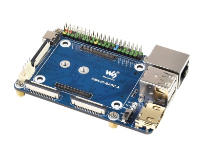
| − | |img=<div class="tabber"><div class="tabbertab" title="CM4-IO-BASE-A">[[File:CM4-IO-BASE-A-1.jpg|400px|link=https://www.waveshare.com/product/cm4-io-base-a.htm]]</div><div class="tabbertab" title="Compute Module 4 ">[[File:Compute-Module-4-1.jpg|400px|alt=Compute Module 4|link=https://www.waveshare.com/compute-module-4.htm]]</div> | + | |img=<div class="tabber"><div class="tabbertab" title="CM4-IO-BASE-A">[[File:CM4-IO-BASE-A-1.jpg|400px|{{Amazon_nolink|default={{#ifeq: {{#urlget:amazon|0}}|{{#urlget:Amazon|0}}| default|}}|url=link=https://www.waveshare.com/product/cm4-io-base-a.htm}}]]</div><div class="tabbertab" title="Compute Module 4 ">[[File:Compute-Module-4-1.jpg|400px|alt=Compute Module 4|{{Amazon_nolink|default={{#ifeq: {{#urlget:amazon|0}}|{{#urlget:Amazon|0}}| default|}}|url=link=https://www.waveshare.com/compute-module-4.htm}}]]</div> |
|caption=Mini Base Board, Composite Breakout Board for Developing with Raspberry Pi CM4 / CM4L | |caption=Mini Base Board, Composite Breakout Board for Developing with Raspberry Pi CM4 / CM4L | ||
|category=[[:Category:Raspberry Pi|Raspberry Pi]] | |category=[[:Category:Raspberry Pi|Raspberry Pi]] | ||
|brand=Waveshare | |brand=Waveshare | ||
| − | |{{#urlget:amazon|default}}=display | + | |{{#ifeq: {{#urlget:amazon|0}}|{{#urlget:Amazon|0}}| default|}}=display |
|website_cn=[https://www.waveshare.net/shop/CM4-IO-BASE-A.htm 中文官网] | |website_cn=[https://www.waveshare.net/shop/CM4-IO-BASE-A.htm 中文官网] | ||
|website_en=[https://www.waveshare.com/product/cm4-io-base-a.htm Website] | |website_en=[https://www.waveshare.com/product/cm4-io-base-a.htm Website] | ||
|related= | |related= | ||
}} | }} | ||
| + | =Overview= | ||
| + | Mini Base Board (A) Designed For Raspberry Pi Compute Module 4. | ||
| + | ==Release Notes== | ||
| − | = | + | Version: CM4-IO-BASE-A V4<br> |
| − | + | 1: Fix the inconsistency between BT-DIS and WIFI-DIS silk screen and actual pins<br> | |
| + | 2: <font color="#ff0000">DSI interface is changed from DSI0 to DSI1, high resolution is supported</font><br> | ||
| − | + | Version: CM4-IO-BASE-A V3.1<br> | |
| − | 1: <font color="#ff0000"> | + | 1: Fix the problem that some CM4 cannot be restarted<br> |
| − | 2: FAN | + | 2: The power supply scheme is modified to improve the output capacity. |
| − | 3: The DSI display interface is the DSI0 interface, and the DSI1 display interface is not connected. <br> | + | |
| − | 4: | + | ==Note== |
| + | 1: <font color="#ff0000">DO NOT unplug any devices other than HDMI and USB when powering on.</font><br> | ||
| + | 2: FAN only supports 5V, and 12V is not supported. Confirm the fan voltage before connecting. This version of the fan does not have a controller and cannot be adjusted in speed. <br> | ||
| + | 3: The DSI display interface is the DSI0 interface, and the DSI1 display interface is not connected. (V4 version starts to display interface for DSI1)<br> | ||
| + | 4: A type C interface can be used for the power supply or a USB SLAVE interface for programming images. <br> | ||
5: In order to ensure the normal power supply of CM4, please do not connect other devices when using the Type C interface to burn the image. <br> | 5: In order to ensure the normal power supply of CM4, please do not connect other devices when using the Type C interface to burn the image. <br> | ||
| − | 6: When CM4 is in normal use, it needs to provide 5V 2A power supply for CM4. Otherwise, problems such as automatic shutdown, frequency reduction, etc. may occur. <br> | + | 6: When CM4 is in normal use, it needs to provide 5V/2A power supply for CM4. Otherwise, problems such as automatic shutdown, frequency reduction, etc. may occur. <br> |
7: When using the M.2 interface, please use the matching screws. Using screws of other lengths may cause the CM4 core to be damaged by the screws. <br> | 7: When using the M.2 interface, please use the matching screws. Using screws of other lengths may cause the CM4 core to be damaged by the screws. <br> | ||
8: The module does not have any protection, please do not short-circuit the power supply. <br> | 8: The module does not have any protection, please do not short-circuit the power supply. <br> | ||
| − | 9: <font color="#ff0000">USB2.0 is closed by default, if you need to open it, you need to add dtoverlay=dwc2,dr_mode=host</font> <br> | + | 9: <font color="#ff0000">USB2.0 is closed by default, if you need to open it, you need to add dtoverlay=dwc2,dr_mode=host.</font> <br> |
| − | 10: If you want to use HDMI1 alone, you can purchase it separately if you need to use it [https://www.waveshare. | + | 10: If you want to use HDMI1 alone, you can purchase it separately if you need to use it [https://www.waveshare.com/hdmi-adapter-horizontal.htm HDMI Adapter].<br> |
| − | 11: Both USB 3/4 and HDMI1 need to be used, you can use [https://www.waveshare. | + | 11: Both USB 3/4 and HDMI1 need to be used, you can use [https://www.waveshare.com/usb-hdmi-adapter.htm adapter board] to connect it out.<br> |
12: This expansion board does not support the POE function.<br> | 12: This expansion board does not support the POE function.<br> | ||
| − | 13: M.2 interface power supply is limited to 1.5A, if it causes problems such as slowing down of solid state or other equipment, it is recommended to buy version B<br> | + | 13: M.2 interface power supply is limited to 1.5A, if it causes problems such as slowing down of solid state or other equipment, it is recommended to buy version B. (V3 version has been fixed)<br> |
| − | + | ==Dimension== | |
| − | CM4-IO-BASE-A<br /> | + | CM4-IO-BASE-A:<br /> |
[[FILE:CM4-IO-BASE-A-details-size.jpg | 680px]]<br> | [[FILE:CM4-IO-BASE-A-details-size.jpg | 680px]]<br> | ||
| − | Compute_Module 4 Core board<br /> | + | Compute_Module 4 Core board:<br /> |
[[FILE:Compute_Module_4_IO_Board_5.png| 680px]]<br> | [[FILE:Compute_Module_4_IO_Board_5.png| 680px]]<br> | ||
| − | + | ==What's on board== | |
| − | |||
[[File:CM4-IO-BASE-A-details-intro.jpg|800px]]<br /> | [[File:CM4-IO-BASE-A-details-intro.jpg|800px]]<br /> | ||
| − | |||
| − | |||
{|border=2; style="width:800px;" | {|border=2; style="width:800px;" | ||
|-style="background:#efffff; color:blue;" align="center" | |-style="background:#efffff; color:blue;" align="center" | ||
| Line 49: | Line 53: | ||
|1||CM4 connector||Suitable for all versions of Compute Module 4 | |1||CM4 connector||Suitable for all versions of Compute Module 4 | ||
|-align="center" | |-align="center" | ||
| − | |style="width:66px"|2||DC power supply/programming interface||5V/2.5A power supply, also can be used as eMMC programming interface | + | |style="width:66px"|2||DC power supply/programming interface||5V/2.5A power supply, also can be used as an eMMC programming interface |
|-align="center" | |-align="center" | ||
| − | |3||DISP Interface||MIPI DSI Display | + | |3||DISP Interface||MIPI DSI Display Interface |
|-align="center" | |-align="center" | ||
| − | |4||FAN | + | |4||FAN header||For connecting cooling fan, allows speed adjustment and measurement, only supports 5V fan. |
|-align="center" | |-align="center" | ||
|5||CAM Interface||Dual MIPI CSI camera interface | |5||CAM Interface||Dual MIPI CSI camera interface | ||
|-align="center" | |-align="center" | ||
| − | |6||HDMI0 Interface||HDMI | + | |6||HDMI0 Interface||HDMI Interface, Support 4K 30fps output |
|-align="center" | |-align="center" | ||
|7||USB 2.0 Interface||2-channel USB 2.0 Interface, for connecting sorts of USB devices | |7||USB 2.0 Interface||2-channel USB 2.0 Interface, for connecting sorts of USB devices | ||
| Line 69: | Line 73: | ||
|11||PWR indicators||Raspberry Pi power indicator | |11||PWR indicators||Raspberry Pi power indicator | ||
|-align="center" | |-align="center" | ||
| − | |12||BOOT selection|| | + | |12||BOOT selection||Jumper shorted: CM4 would be booted from USB-C interface <br />Jumper opened: CM4 would be booted from eMMC or Micro SD card |
|-align="center" | |-align="center" | ||
| − | |13||40PIN GPIO | + | |13||40PIN GPIO header||Conveniently connect various HAT modules |
|-align="center" | |-align="center" | ||
| − | |14||Micro SD Card | + | |14||Micro SD Card Slot||For connecting a Micro SD card with a pre-burnt image (Lite variant ONLY). |
|-align="center" | |-align="center" | ||
| − | |15||HDMI1 interface||HDMI1 | + | |15||HDMI1 interface||HDMI1 Interface, Support 4K 30fps output |
|-align="center" | |-align="center" | ||
| − | |16||USB 2.0 | + | |16||USB 2.0 connector||Can be connected through an adapter |
|-align="center" | |-align="center" | ||
|17||FE1.1S||USB HUB chip, expanding one USB port to 4x ports | |17||FE1.1S||USB HUB chip, expanding one USB port to 4x ports | ||
| Line 83: | Line 87: | ||
|18||M.2 Interface||Supports sorts of NVME SSD, or communication modules with PCIE M.2 KEY-M interface | |18||M.2 Interface||Supports sorts of NVME SSD, or communication modules with PCIE M.2 KEY-M interface | ||
|} | |} | ||
| − | |||
| − | |||
| − | |||
| − | |||
| − | |||
| − | |||
==Precautions== | ==Precautions== | ||
| − | <font color="#ff0000">Do not plug or unplug any device while it is powered on</font><br> | + | <font color="#ff0000">Do not plug or unplug any device while it is powered on.</font><br> |
| − | |||
==Writing Image== | ==Writing Image== | ||
| Line 99: | Line 96: | ||
==USB2.0== | ==USB2.0== | ||
| + | <font color="#ff00ff"> | ||
| + | CM4 Error:<br/> | ||
| + | </font> | ||
| + | config failed, hub doesn't have any ports! (err -19) | ||
| + | <font color="#ff00ff">However, the USB can still be used. If you want to remove this error, remove "otg_mode=1" in [cm4] of config.txt, and add "dtoverlay=dwc2, dr_mode=host" (USB cannot be recognized without adding it). <br></font> | ||
| + | <!-- | ||
The USB port is disabled by default on the CM4 to save power. If you need to start, you need to add the following to the config.txt file: | The USB port is disabled by default on the CM4 to save power. If you need to start, you need to add the following to the config.txt file: | ||
dtoverlay=dwc2,dr_mode=host | dtoverlay=dwc2,dr_mode=host | ||
After restarting <br> | After restarting <br> | ||
| − | |||
<font color="#ff00ff"> | <font color="#ff00ff"> | ||
If you use the latest Raspberry Pi OS (image after October 30, 2021) USB2.0 is OTG mode by default, CM4 will report an error: <br> | If you use the latest Raspberry Pi OS (image after October 30, 2021) USB2.0 is OTG mode by default, CM4 will report an error: <br> | ||
config failed, hub doesn't have any ports! (err -19) | config failed, hub doesn't have any ports! (err -19) | ||
However, USB can still be used. If you want to remove this error, remove otg_mode=1 in [cm4] of config.txt, and add dtoverlay=dwc2, dr_mode=host (USB cannot be recognized without adding it). <br> | However, USB can still be used. If you want to remove this error, remove otg_mode=1 in [cm4] of config.txt, and add dtoverlay=dwc2, dr_mode=host (USB cannot be recognized without adding it). <br> | ||
| + | --> | ||
[[FILE:CM4 Burn EMMC_12.png|800px]]<br> | [[FILE:CM4 Burn EMMC_12.png|800px]]<br> | ||
| − | <br> | + | If the USB does not work, you need to add the following to the config .txt file:<br> |
| − | + | dtoverlay=dwc2,dr_mode=host | |
| + | Then reboot. | ||
| + | |||
| + | ==M.2== | ||
| + | The M.2 interface type is M KEY, which only supports PCIE channel devices (including NVME solid state, etc.), and does not support SATA hard disks. | ||
| + | :[[File:CM4-IO-BASE-A-1-4.jpg|600px]] | ||
| + | Support some type of adapter cards by using the PCIE channel. Some types of cards cannot be driven by the official Raspberry Pi image, it needs to recompile the kernel. | ||
==FAN== | ==FAN== | ||
| − | The PWM pin of the FAN is connected to the GPIO18 of the CM4 board. | + | '''The PWM pin of the FAN is connected to the GPIO18 of the CM4 board.'''<br> |
| + | For an example of controlling the fan speed using the Pi GPIOs, see this page: https://www.waveshare.com/wiki/PI4-FAN-PWM#How_to_enable_it_via_Programming | ||
==CSI DSI== | ==CSI DSI== | ||
| − | CSI | + | The V4 version starts to use the DSI1 interface, select the corresponding command when compiling the corresponding file.<br> |
| + | {{CM4-CSI-DSI2}} | ||
| + | <!-- | ||
| + | ===Config File=== | ||
| + | CSI and DSI are disabled by default. When using the camera and DSI, it will occupy three I2C devices: I2C-10, I2C-11, and I2C-0.<br> | ||
*Open a terminal and run the following commands:<br> | *Open a terminal and run the following commands:<br> | ||
<source lang="c"> | <source lang="c"> | ||
| − | + | wget https://files.waveshare.com/upload/7/75/CM4_dt_blob_Source.zip | |
| − | wget https:// | + | unzip -o CM4_dt_blob_Source.zip -d ./CM4_dt_blob_Source |
| − | + | sudo chmod 777 -R CM4_dt_blob_Source | |
| − | sudo chmod 777 -R | + | cd CM4_dt_blob_Source/ |
| − | cd | + | #If you want to use two cameras and DSI0, please execute |
| − | #If you want to use | ||
sudo dtc -I dts -O dtb -o /boot/dt-blob.bin dt-blob-disp0-double_cam.dts | sudo dtc -I dts -O dtb -o /boot/dt-blob.bin dt-blob-disp0-double_cam.dts | ||
| − | #If you want to | + | #If you want to use two cameras and DSI1, please execute |
sudo dtc -I dts -O dtb -o /boot/dt-blob.bin dt-blob-disp1-double_cam.dts | sudo dtc -I dts -O dtb -o /boot/dt-blob.bin dt-blob-disp1-double_cam.dts | ||
| + | #When using any DSI interface, HDMI1 will have no image output, even if you do not connect the DSI screen, as long as you compile the corresponding file, then HDMI1 will not output | ||
| + | #If you need to restore, please delete the corresponding dt-blob.bin: sudo rm -rf /boot/dt-blob.bin | ||
| + | # After execution, turn off the power and restart the CM4 | ||
</source> | </source> | ||
| − | + | ===Recording test=== | |
| − | 1: Please power off the IO Board first before | + | And then connect the cameras and DSI display;<br> |
| + | 1: Please power off the IO Board first before connecting.<br> | ||
| + | 2: Connet the power supply. | ||
| + | 3: The screen will boot up after waiting for a few seconds. | ||
| + | 4: If the screen cannot be booted up, please check if you have added /boot/dt-blob.bin. If there already has the dt-blob.bin, just try to reboot. | ||
| + | <!-- | ||
2: Connect the power adapter after connecting the cameras and DSI display<br> | 2: Connect the power adapter after connecting the cameras and DSI display<br> | ||
3: Wait a few seconds before the screen boot up.<br> | 3: Wait a few seconds before the screen boot up.<br> | ||
4: If the DSI LCD cannot display, please check if you have added /boot/dt-blob.bin. If there already has the dt-blob.bin, just try to reboot.<br> | 4: If the DSI LCD cannot display, please check if you have added /boot/dt-blob.bin. If there already has the dt-blob.bin, just try to reboot.<br> | ||
5: The camera needs to be enabled by raspi-config, enter sudo raspi-config on the terminal, choose Interfacing Options->Camera->Yes->Finish-Yes and reboot the system<br> | 5: The camera needs to be enabled by raspi-config, enter sudo raspi-config on the terminal, choose Interfacing Options->Camera->Yes->Finish-Yes and reboot the system<br> | ||
| + | --> | ||
| − | * | + | =Resource= |
| − | + | ==Document== | |
| − | + | *[https://files.waveshare.com/upload/a/aa/CM4-IO-BASE-A_SchDoc.pdf Schematic V1] | |
| − | + | *[https://files.waveshare.com/upload/a/aa/CM4-IO-BASE-A_V4_SchDoc.pdf Schematic V4] | |
| − | |||
| − | |||
| − | |||
| − | |||
| − | |||
| − | |||
| − | |||
| − | |||
| − | |||
| − | |||
| − | |||
| − | |||
| − | |||
| − | |||
| − | *[https:// | ||
*[https://www.raspberrypi.org/documentation/hardware/computemodule/cmio-camera.md CSI Camera Reference] | *[https://www.raspberrypi.org/documentation/hardware/computemodule/cmio-camera.md CSI Camera Reference] | ||
*[https://www.raspberrypi.org/documentation/hardware/computemodule/cmio-display.md DSI Display Reference] | *[https://www.raspberrypi.org/documentation/hardware/computemodule/cmio-display.md DSI Display Reference] | ||
| − | + | ==3D Drawing== | |
| − | *[https:// | + | *[https://files.waveshare.com/upload/f/fb/CM4-IO-BASE.7z 3D Drawing]<br> |
| − | |||
| − | |||
| − | |||
| − | |||
| − | |||
| − | |||
| − | |||
| − | |||
| − | |||
| − | |||
| − | |||
| − | |||
| − | |||
| − | |||
| − | |||
| + | ==Demo codes== | ||
| + | *[https://files.waveshare.com/upload/3/31/CM4_Code.zip Demo] | ||
| + | ==Software== | ||
| + | *[https://files.waveshare.com/upload/d/d7/Panasonic_SDFormatter.zip Panasonic_SDFormatter-Formatting SD card] | ||
| + | *[https://files.waveshare.com/upload/7/76/Win32DiskImager.zip Win32DiskImager] | ||
| + | *[https://files.waveshare.com/upload/5/56/Putty.zip Putty] | ||
| + | *[https://files.waveshare.com/upload/f/f3/Rpiboot_setup.zip RPiboot_Setup] | ||
| − | </ | + | =FAQ= |
| − | + | {{FAQ|What should I do if the I2C address of the RTC/FAN controller cannot be searched using i2cdetect -y 10? | |
| + | |a) Check whether dtparam -audio - on is blocked in /boot/config.txt <br /> | ||
| + | b) Check whether the /boot/dt-blob.bin file exists, if it cannot be used, delete it;|||}} | ||
| + | =Support= | ||
| + | {{Servicebox1}}<br> | ||
If it is a technical problem, you can contact me directly: <br> | If it is a technical problem, you can contact me directly: <br> | ||
https://join.skype.com/invite/WI7vBbbvPf98<br> | https://join.skype.com/invite/WI7vBbbvPf98<br> | ||
</div> | </div> | ||
</div> | </div> | ||
Latest revision as of 10:10, 25 March 2024
| ||

Overview
Mini Base Board (A) Designed For Raspberry Pi Compute Module 4.
Release Notes
Version: CM4-IO-BASE-A V4
 1: Fix the inconsistency between BT-DIS and WIFI-DIS silk screen and actual pins

 2: DSI interface is changed from DSI0 to DSI1, high resolution is supported
Version: CM4-IO-BASE-A V3.1
 1: Fix the problem that some CM4 cannot be restarted

 2: The power supply scheme is modified to improve the output capacity.
Note
1: DO NOT unplug any devices other than HDMI and USB when powering on.
2: FAN only supports 5V, and 12V is not supported. Confirm the fan voltage before connecting. This version of the fan does not have a controller and cannot be adjusted in speed.
3: The DSI display interface is the DSI0 interface, and the DSI1 display interface is not connected. (V4 version starts to display interface for DSI1)
4: A type C interface can be used for the power supply or a USB SLAVE interface for programming images.
5: In order to ensure the normal power supply of CM4, please do not connect other devices when using the Type C interface to burn the image.
6: When CM4 is in normal use, it needs to provide 5V/2A power supply for CM4. Otherwise, problems such as automatic shutdown, frequency reduction, etc. may occur.
7: When using the M.2 interface, please use the matching screws. Using screws of other lengths may cause the CM4 core to be damaged by the screws.
8: The module does not have any protection, please do not short-circuit the power supply.
9: USB2.0 is closed by default, if you need to open it, you need to add dtoverlay=dwc2,dr_mode=host.
10: If you want to use HDMI1 alone, you can purchase it separately if you need to use it HDMI Adapter.
11: Both USB 3/4 and HDMI1 need to be used, you can use adapter board to connect it out.
12: This expansion board does not support the POE function.
13: M.2 interface power supply is limited to 1.5A, if it causes problems such as slowing down of solid state or other equipment, it is recommended to buy version B. (V3 version has been fixed)
Dimension
CM4-IO-BASE-A:

Compute_Module 4 Core board:

What's on board

| No. | Component | Description |
| 1 | CM4 connector | Suitable for all versions of Compute Module 4 |
| 2 | DC power supply/programming interface | 5V/2.5A power supply, also can be used as an eMMC programming interface |
| 3 | DISP Interface | MIPI DSI Display Interface |
| 4 | FAN header | For connecting cooling fan, allows speed adjustment and measurement, only supports 5V fan. |
| 5 | CAM Interface | Dual MIPI CSI camera interface |
| 6 | HDMI0 Interface | HDMI Interface, Support 4K 30fps output |
| 7 | USB 2.0 Interface | 2-channel USB 2.0 Interface, for connecting sorts of USB devices |
| 8 | Gigabit Ethernet | Gigabit Ethernet RJ45 connector, with 10 / 100 / 1000M network support |
| 9 | M.2 indicators | Indicating the operating status of M.2 interface |
| 10 | ACT indicators | Raspberry Pi operating status indicator |
| 11 | PWR indicators | Raspberry Pi power indicator |
| 12 | BOOT selection | Jumper shorted: CM4 would be booted from USB-C interface Jumper opened: CM4 would be booted from eMMC or Micro SD card |
| 13 | 40PIN GPIO header | Conveniently connect various HAT modules |
| 14 | Micro SD Card Slot | For connecting a Micro SD card with a pre-burnt image (Lite variant ONLY). |
| 15 | HDMI1 interface | HDMI1 Interface, Support 4K 30fps output |
| 16 | USB 2.0 connector | Can be connected through an adapter |
| 17 | FE1.1S | USB HUB chip, expanding one USB port to 4x ports |
| 18 | M.2 Interface | Supports sorts of NVME SSD, or communication modules with PCIE M.2 KEY-M interface |
Precautions
Do not plug or unplug any device while it is powered on.
Writing Image
- Write Image for Compute Module Boards eMMC version
- Write Image for Compute Module Boards Lite version
USB2.0
CM4 Error:
config failed, hub doesn't have any ports! (err -19)
However, the USB can still be used. If you want to remove this error, remove "otg_mode=1" in [cm4] of config.txt, and add "dtoverlay=dwc2, dr_mode=host" (USB cannot be recognized without adding it).

If the USB does not work, you need to add the following to the config .txt file:
dtoverlay=dwc2,dr_mode=host
Then reboot.
M.2
The M.2 interface type is M KEY, which only supports PCIE channel devices (including NVME solid state, etc.), and does not support SATA hard disks.

Support some type of adapter cards by using the PCIE channel. Some types of cards cannot be driven by the official Raspberry Pi image, it needs to recompile the kernel.
FAN
The PWM pin of the FAN is connected to the GPIO18 of the CM4 board.
For an example of controlling the fan speed using the Pi GPIOs, see this page: https://www.waveshare.com/wiki/PI4-FAN-PWM#How_to_enable_it_via_Programming
CSI DSI
The V4 version starts to use the DSI1 interface, select the corresponding command when compiling the corresponding file.
Configuration file
CSI and DSI are disabled by default. When using the camera and DSI, it will occupy three I2C devices: I2C-10, I2C-11, and I2C-0.
- Open a terminal and run the following commands:
sudo apt-get install p7zip-full -y
wget https://files.waveshare.com/upload/7/75/CM4_dt_blob_Source.zip
7z x CM4_dt_blob.7z -O./CM4_dt_blob
sudo chmod 777 -R CM4_dt_blob
cd CM4_dt_blob/
# If using two cameras and DSI1 execute
sudo dtc -I dts -O dtb -o /boot/dt-blob.bin dt-blob-disp1-double_cam.dts
# In the use of any DSI, HDMI1 no image output, even if you do not connect the DSI screen as long as the corresponding file compiled, that HDMI1 no output
# If you need to restore, delete the corresponding dt-blob.bin can be: sudo rm -rf /boot/dt-blob.bin
#Execution is complete, power off and restart CM4
New Version (Bullseye)
Camera Config
-
Execute the following commands to edit "/boot/config.txt" file.
sudo nano /boot/config.txt
-
Block or remove the automatic camera detection statement:
-
Add the driver of the camera you are using, here I take IMX219 as an example and connect it to CAM0, and attach the adapter.
Model CAM0 Set Sentence CAM1 Set Sentence OV9281 dtoverlay=ov9281,cam0 dtoverlay=ov9281,cam1 IMX290/IMX327 dtoverlay=imx290,clock-frequency=37125000,cam0 dtoverlay=imx290,clock-frequency=37125000,cam1 IMX378 dtoverlay=imx378,cam0 dtoverlay=imx378,cam1 IMX219 dtoverlay=imx219,cam0 dtoverlay=imx219,cam1 IMX477 dtoverlay=imx477,cam0 dtoverlay=imx477,cam1 IMX708 dtoverlay=imx708,cam0 dtoverlay=imx708,cam1 - If you are using the official Raspberry Pi camera and only one camera is connected, there is no need to set the config file. If it is not an official camera, set the "dtoverlay" statement without the "cam" suffix.
- CM4-NANO - only CAM0 is used, so you only need to add "dtoverlay=imx219,cam0".


5. Ctrl+x to exit the editor.
6. Reboot the Raspberry Pi.
sudo reboot
Camera Test
- Enter the camera detection command, you can see that the camera is detected by now.
libcamera-hello --list-cameras

- Display the camera screen on the desktop.
- Taking photos.
libcamera-jpeg -o test.jpg
- Record a video of 10s.
libcamera-vid -t 10000 -o test.h264
Other Commands

libcamera-hello -t
Check whether the camera is detected:
libcamera-hello --list-cameras
Open the corresponding cameras:
libcamera-hello  --camera 1
libcamera-hello  --camera 0
Take a photo:
libcamera-jpeg -o test.jpg
#Add --camera to specify a camera
Old Version (Buster)
Camera Config
-
1. Execute the following command to enter the Raspberry Pi configuration.
- Test the recording function:
- Where -t 10000 means recording for 10 seconds, users can adjust according to their own needs.
- Please refer to CSI.
sudo raspi-config
2. Choose Interfacing Options and enter.

3. Choose Camera:

4. Choose to enable the camera interface.

5. The system prompts as follows:

6. Back to the main interface, select Finish.

7. Reboot the system.

Camera Test
raspistill -o image.jpg
raspivid -o video.h264 -t 10000
Resource
Document
3D Drawing
Demo codes
Software
FAQ
b) Check whether the /boot/dt-blob.bin file exists, if it cannot be used, delete it;
Support
Technical Support
If you need technical support or have any feedback/review, please click the Submit Now button to submit a ticket, Our support team will check and reply to you within 1 to 2 working days. Please be patient as we make every effort to help you to resolve the issue.
Working Time: 9 AM - 6 AM GMT+8 (Monday to Friday)
If it is a technical problem, you can contact me directly:
https://join.skype.com/invite/WI7vBbbvPf98