
CM4-ETH-RS485-BASE-B
| ||
| ||
| ||


Introduction
Detailed parameter and function description.
Product Description
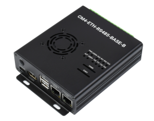
My name is CM4-ETH-RS485-BASE-B, which is an expansion board that can be used with Raspberry Pi Compute Module 4, and supports a 7-36V DC power supply and 5V DC power supply of Type-C interface. Onboard four isolated RS485 interfaces, 100M+1000M dual network ports, HDMI interface, two CSI interfaces, two USB interfaces, etc...
Precautions for use
- Do not plug and unplug any device except USB and HDMI when it is powered on.
- Confirm the fan voltage before connecting, only support 5V.
- The Type C interface can be used as a power supply or as a USB interface to burn the image (need to use the DIP switch to switch).
- In order to ensure the normal power supply of CM4, please do not connect other devices when using the Type C interface to burn the image.
- When CM4 is in normal use, it needs to provide a 5V 2A power supply for CM4. Otherwise, there may be problems such as automatic shutdown, frequency reduction, and so on.
- USB2.0 is closed by default, if you need to open it, you need to add dtoverlay=dwc2,dr_mode=host in config.txt.
Product Size
CM4-ETH-RS485-BASE-B

Compute_Module 4 core board

Onboard resources

Interfaces
| Label | Name | Instruction |
| 1 | CM4 connector | Applicable to all editions of Compute Module 4 |
| 2 | IO-VREF | Select GPIO logic voltage, selectable 3.3V (default) or 1.8V |
| 3 | RTC-I2C:I2C bus selection for RTC | Optional SDA0 & SCL0 (default) or GPIO2 & GPIO3 |
| 4 | RTC INT:RTC Interrupt pin selection | D16:RTC Use GPIO16 to receive interrupt signal when generating interrupt (default) GL-EN: CM4 is powered off when RTC generates an interrupt |
| 5 | SYSTEM:System Function | WP-DIS: Prevent EEPROM from being overwritten BT-DIS: Disable Bluetooth function, only works on CM4 version with antenna |
| 6 | BOOT Switch | ON: Boot as USB Type-C interface OFF: Boot to eMMC or Micro SD card |
| 7 | PWR & USB | When the BOOT switch is "ON", it can be used as a programming port and a power supply interface When the BOOT switch is "OFF", it is only used as a power supply interface |
| 8 | HDMI0 | HDMI Display interface, support 4K 30fps output |
| 9 | USB | Two-way USB2.0 interface, support USB device insertion |
| 10 | ETHERNET0 | CM4 native Gigabit RJ45 Ethernet port |
| 11 | ETHERNET1 | USB expansion 100M Ethernet port |
| 12 | CAM0 & CAM1 | Two MIPI CSI camera interfaces |
| 13 | Buzzer | GPIO22 control |
| 14 | FAN | Four-wire fan interface, only supports 5V fans, PWM speed regulation (GPIO18 control, no speed measurement) |
| 15 | RTC Battery interface | can be connected to the CR1220 button battery |
| 16 | RS485 Transceiver indicator | TXn: transmit information indicator of channel n RXn: Receive information indicator for channel n |
| 17 | User LED light | USER0: GPIO20 control USER1: GPIO26 control |
| 18 | PWR | Raspberry Pi power indicator |
| 19 | ACT | Raspberry Pi working status indicator |
| 20 | DC 7~36V | DC power supply interface |
| 21 | Power supply terminal | DC power supply terminal, support 7~36V wide voltage input |
| 22 | RS485 Terminal | Four-way isolated RS485 interface, pitch 5.08mm |
| 23 | Jumper Cap | Optional 120R Balance Resistor Jumper Cap |
| 24 | RS485 mode switch | Full-auto: automatic mode, the program operation is simple, the load capacity is weak Semi-auto: semi-automatic mode, need to manually switch the transceiver mode, high reliability, strong load capacity |
| 25 | Encryption chip | ATSHA204 encryption chip, which can perform multiple encryptions to ensure data security and reliability |
| 26 | Micro SD card slot | For inserting a Micro SD card with the system to start the Compute Module 4 Lite |
How to use
Precautions
Do not plug or unplug any device while it is powered on.
Image Burning
EMMC version click here
LITE version click here
USB 2.0
USB2.0 is disabled by default, if you want to enable it, you need to add dtoverlay=dwc2,dr_mode=host in config.txt
RS485
It is closed by default. If you want to open it, you need to add content in config.txt:
sudo nano /boot/config.txt
dtoverlay=uart0
dtoverlay=uart3
dtoverlay=uart4
dtoverlay=uart5
COM0 occupies GPIO14/GPIO15 (BCM code 14/15), device number ttyAMA0.
COM1 occupies GPIO4/GPIO5 (BCM code 4/5), device number ttyAMA1.
COM2 occupies GPIO8/GPIO9 (BCM code 8/9), device number ttyAMA2.
COM3 occupies GPIO12/GPIO13 (BCM code 12/13), device number ttyAMA3.
If other serial ports are opened, the comments need to be closed, for example:
#enable_uart=1
Note: the default mode is semi-automatic, which requires program control of transceiver mode; The 0R resistor on the back can be modified if automatic sending and receiving is required.
- Mode switching: each channel is controlled by two 0R resistors.
- Semi-automatic mode: the 0R resistor is on the "Semi-auto" end, and the user program controls the transceiver mode.
- Full-automatic mode: The 0R resistor is on the "Full-auto" end, and the transceiver mode is automatically switched according to the transmission direction.

RTC
Enable I2C to connect to the RTC controller, you need to set the dtparam=i2c_vc=on configuration file. RTC is on i2c-10, address is 0 x 51 (7-bit address).
sudo nano /boot/config.txt
#Add at the end
dtparam=i2c_vc=on
#Add # in front of dtparam=audio=on
#dtparam=audio=on
#Save and exit, restart
sudo reboot
Downloader
Open the Raspberry Pi terminal and execute the following commands:
sudo apt-get install p7zip-full
sudo wget https://www.waveshare.net/w/upload/4/42/PCF85063_code.7z
7z x PCF85063_code.7z -O./
cd PCF85063_code
C code
Execute the following instructions to compile and execute the test program:
cd c
sudo make clean
sudo make -j 8
sudo ./main
The experimental phenomenon is as follows:

Python
Enter the python program directory:
cd python/example
Run the demo, the program supports python2/3
# python2
sudo python main.py
# python3
sudo python3 main.py
The experimental phenomenon is as follows:

FAN test
- Support PWM speed regulation, no speed detection function
- Note: Before connecting, please confirm the fan voltage and the power supply of the actually connected fan
Open the Raspberry Pi terminal and execute the following commands:
wget https://www.waveshare.com/w/upload/d/d1/CM4-ETH-RS485-BASE-B-Example.zip
unzip CM4-ETH-RS485-BASE-B-Example.zip -d ./CM4-ETH-RS485-BASE-B-Example
cd CM4-ETH-RS485-BASE-B-Example/FAN/
c code
Compile and execute the test program
cd c
sudo make clean
sudo make
sudo ./main
Phenomenon: Enter the duty cycle as prompted to change the fan speed
python
Enter the python program directory
cd python
Run the routine, the program supports python2/3
# python2
sudo python FAN.py
# python3
sudo python3 FAN.py
Phenomenon: first press the prompt to input the frequency, 5K is recommended, and then cycle the input duty cycle to change the fan speed.
CSI
Note: The following is the general description of CM4, the specific equipment is different: this module has no DSI interface, and only HDMI0.
configuration file
CSI and DSI are disabled by default. When using camera and DSI, three I2C devices, I2C-10, I2C-11, and I2C-0, will be occupied.
Start up as follows:
wget https://www.waveshare.com/w/upload/7/75/CM4_dt_blob_Source.zip
 unzip -o  CM4_dt_blob_Source.zip -d ./CM4_dt_blob_Source
 sudo chmod 777 -R CM4_dt_blob_Source
 cd CM4_dt_blob_Source/
 #If using two cameras and DSI0 execute
  sudo dtc -I dts -O dtb -o /boot/dt-blob.bin dt-blob-disp0-double_cam.dts
  #If using two cameras and DSI1 execute
  sudo dtc -I dts -O dtb -o /boot/dt-blob.bin dt-blob-disp1-double_cam.dts
  #When using any DSI, HDMI1 has no image output, even if you do not connect the DSI screen, as long as you compile the corresponding file, then HDMI1 will not output
  #If you need to restore, delete the corresponding dt-blob.bin: sudo rm -rf /boot/dt-blob.bin
  # After execution, turn off the power and restart the CM4
Recording test
Then connect the camera and DSI screen:
- Make sure the connection is in the power-off state
- Connect Power
- Wait a few seconds for the screen to start up
- If it fails to start, check whether /boot/dt-blob.bin exists, and restart it if it exists.
- The camera needs to run raspi-config, select Interfacing Options->Camera->Yes->Finish-Yes, reboot the system, open the enable camera, and then restart to save the changes.
Old Version (Buster)
Test the Raspberry Pi camera View the first camera connected to the screen:
sudo raspivid -t 0 -cs 0
View the picture of the second camera connected:
sudo raspivid -t 0 -cs 1
New Version (Buster)
If using the latest Raspberry Pi OS (Bullseye):
libcamera-hello -t 0
or
libcamera-hello

#Using dual cameras in the new system
#Remove camera_auto_detect=1 in config.text
#camera_auto_detect=1

#add
dtoverlay=imx219,cam1
dtoverlay=imx219,cam0

#imx219 is the model of the camera sensor and other sensor
dtoverlay=ov5647,cam0
dtoverlay=imx219,cam0
dtoverlay=ov9281,cam0
dtoverlay=imx477,cam0

#then reboot
reboot

# other commands
#check whether the camera is detected
libcamera-hello --list-cameras

#open the corresponding camera
libcamera-hello --camera 1
libcamera-hello --camera 0

#take photo
libcamera-jpeg -o test.jpg
#Also you can add --camera to choose the camera
More commands Click here
- NOTE: If using the DSI interface the display will have an HDMI disabled, even if just compiling the corresponding file without connecting the DSI screen.
- Any connection of two HDMIs can output images, not limited to that HDMI. If two HDMI screens are connected, only HDMI0 has image output.
- If you want to enable both HDMI, delete the dt-blob.bin file with the following command:
sudo rm -rf /boot/dt-blob.bin
- And then restart
Refer to the Raspberry Pi manual
Encryption
Onboard encryption chip, not enabled by default
Please refer to the data sheet and official library for use: [1]
Resources
Provide a full set of documents, procedures, data sheets, etc.
Documentation
Schematic
3D map
Program
Software
- RPiboot_Setup
- Panasonic_SDFormatter-formatting software
- Win32DiskImager-Download image software
- putty
FAQ
b) Check whether the /boot/dt-blob.bin file exists, if it cannot be used, please delete it;
{{{5}}}
Support
If you require technical support, please go to the Support page and open a ticket.