
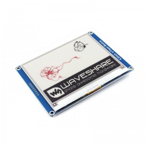
4.2inch e-Paper Module (B)
| ||
| ||

Introduction
Note: As the raw panel requires a driver board, we recommend you to buy the HAT or buy a driver board for use, or you need to make the driver board by yourself. And this instruction is based on the version with PCB or driver board.
400x300, 4.2inch E-Ink display module, three-color, SPI interface
| More |
Interfaces
| VCC | 3.3V |
| GND | GND |
| DIN | SPI MOSI |
| CLK | SPI SCK |
| CS | SPI chip select (Low active) |
| DC | Data/Command control pin (High for data, and low for command) |
| RST | External reset pin (Low for reset) |
| BUSY | Busy state output pin (Low for busy) |
Working principle
- Introduction
This product is an E-paper device adopting the image display technology of Microencapsulated Electrophoretic Display, MED. The initial approach is to create tiny spheres, in which the charged color pigments are suspending in the transparent oil and would move depending on the electronic charge. The E-paper screen display patterns by reflecting the ambient light, so it has no background light requirement. Under sunshine, the E-paper screen still has high visibility with a wide viewing angle of 180 degree. It is the ideal choice for E-reading.
- Communication protocol

Note: Different from the traditional SPI protocol, the data line from the slave to the master is hidden since the device only has display requirement.
- CS is slave chip select, when CS is low, the chip is enabled.
- DC is data/command control pin, when DC = 0, write command, when DC = 1, write data.
- SCLK is the SPI communication clock.
- SDIN is the data line from the master to the slave in SPI communication.
SPI communication has data transfer timing, which is combined by CPHA and CPOL.
- CPOL determines the level of the serial synchronous clock at idle state. When CPOL = 0, the level is Low. However, CPOL has little effect to the transmission.
- CPHA determines whether data is collected at the first clock edge or at the second clock edge of serial synchronous clock; when CPHL = 0, data is collected at the first clock edge.
- There are 4 SPI communication modes. SPI0 is commonly used, in which CPHL = 0, CPOL = 0.
As you can see from the figure above, data transmission starts at the first falling edge of SCLK, and 8 bits of data are transferred in one clock cycle. In here, SPI0 is in used, and data is transferred by bits, MSB first.
Resources
Documentation
Demo code
Datasheets
Related Resources
This is a post in Arduino Form about our SPI e-Paper thanks to ZinggJM, maybe you want to refer to.
FAQ
- Two-color B/W e-paper
- 【Working】Temperature: 0~50°C; Humidity: 35%~65%RH
- 【Storage】Temperature: ≤30°C; Humidity: ≤55%RH; Max storage time: 6 months
- 【Transport】Temperature: -25~70°C; Max transport time: 10 days
- 【Unpack】Temperature: 20°C±5°C; Humidity: 50%RH±5%RH; Max storage time: Should be assembled in 72h
- Three-Color e-Paper
- 【Working】Temperature: 0~40°C; Humidity: 35%~65%RH
- 【Storage】Temperature: ≤30°C; Humidity: ≤55%RH; Max storage time: 3 months
- 【Transport】Temperature: -25~60°C; Max transport time: 10 days
- 【Unpack】Temperature: 20°C±5°C; Humidity: 50%RH±5%RH; Max storage time: Should be assembled in 72h
When store three-color e-Paper, please refresh it to white, and keep the screen upward. Note that you need to update it at least every three months.
Support
Support
If you require technical support, please go to the Support page and open a ticket.