
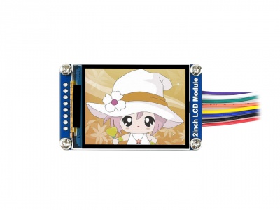
2inch LCD Module
| ||
Instruction
This is a general LCD display Module, IPS screen, 2inch diagonal, 240×320 resolution, with embedded controller, communicating via SPI interface
Feature
- SPI interface requires minimum GPIO for controlling
- Comes with development resources and manual
- The basic functions have been encapsulated on the demo, which can realize picture rotation, draw dots, lines, circles, rectangles, display English characters and Chinese characters, and display pictures.
Specifications
- Operating voltage: 3.3V/5V
- Interface: SPI
- LCD type: IPS
- Controller: ST7789V
- Resolution: 240(V) x 320(H)RGB
- Display size: 30.60(H)x 40.80(V)mm
- Pixel size: 0.0975(H)x 0.0975(V)mm
- Dimension: 58 x 35(mm)
Interface
| SYMBOL | Description |
| VCC | Power (3.3V input) |
| GND | Ground |
| DIN | SPI data input |
| CLK | SPI clock input |
| CS | Chip selection, low active |
| DC | Data/Command selection (high for data, low for command) |
| RST | Reset, low active |
| BL | Backlight |
Hardware description
ST7789V supports RGB444, RGB565 and RGB666 three formats. This LCD uses RGB565.
For most LCD controllers, the communication method of the controller can be configured, they are usually using 8080 parallel interface, 3-line SPI, 4-line SPI, and other communication methods. This LCD uses a 4-line SPI interface for reducing GPIO and fast speed.LCD
Communication protocol

Note: It is not like the tradition SPI protocol, it only uses MOSI to send data from master to slave for LCD display. For details please refer to Datasheet Page 105.
RESX: Reset, should be pull-down when power on, set to 1 other time.
CSX: Slave chip select. The chip is enabled only CS is set Low
D/CX: Data/Command selection; DC=0, write command; DC=1, write data
SDA: Data transmitted. (RGB data)
SCL: SPI clock
The SPI communication protocol of the data transmission uses control bits: clock phase (CPHA) and clock polarity (CPOL):
CPOL defines the level while the synchronization clock is idle. If CPOL=0, then it is LOW.
CPHA defines at whish clock’s tick the data transmission starts. CPHL=0 – at the first one, otherwise at the second one
This combination of two bits provides 4 modes of SPI data transmission. The commonly used is SPI0 mode, i.e. GPHL=0 and CPOL=0.
According to the figure above, data transmitting begins at the first falling edge, 8bit data are transmitted at one clock cycle. It is SPI0. MSB.
Hardware connection
Please connect the LCD to your Raspberry Pi by the 8PIn cable according to the table below
| LCD | Raspberry Pi | |
| BCM2835 | Board | |
| VCC | 5V | 5V |
| GND | GND | GND |
| DIN | MOSI | 19 |
| CLK | SCLK | 23 |
| CS | CE0 | 24 |
| DC | 25 | 22 |
| RST | 27 | 13 |
| BL | 18 | 12 |
The color of actual cable may be different with the figure here, please connect them according to the pins instead of color.

Enable SPI interface
- Open terminal, use command to enter the configuration page
sudo raspi-config
Choose Interfacing Options -> SPI -> Yes  to enable SPI interface

Reboot Raspberry Pi:
sudo reboot
Please make sure that SPI interface was not used by other devices
Install Libraries
- Install BCM2835 libraries
wget http://www.airspayce.com/mikem/bcm2835/bcm2835-1.68.tar.gz
tar zxvf bcm2835-1.68.tar.gz
cd bcm2835-1.68/
sudo ./configure
sudo make
sudo make check
sudo make install
#For more details, please refer to http://www.airspayce.com/mikem/bcm2835/
- Install wiringPi libraries
sudo apt-get install wiringpi
For the version of the Raspberry Pi system after May 2019 (the OS version earlier than this date doesn't need to be executed), an upgrade may be required:
wget https://project-downloads.drogon.net/wiringpi-latest.deb
sudo dpkg -i wiringpi-latest.deb
gpio -v
#You will get 2.52 information if you install it correctly
- Install Python libraries
#python2
sudo apt-get update
sudo apt-get install python-pip
sudo apt-get install python-pil
sudo apt-get install python-numpy
sudo pip install RPi.GPIO
sudo pip install spidev
#python3
sudo apt-get update
sudo apt-get install python3-pip
sudo apt-get install python3-pil
sudo apt-get install python3-numpy
sudo pip3 install RPi.GPIO
sudo pip3 install spidev
Download Examples
Open Raspberry Pi terminal and run the following command
sudo apt-get install p7zip-full
sudo wget  https://files.waveshare.com/upload/a/a8/LCD_Module_RPI_code.7z
7z x LCD_Module_RPI_code.7z -O./LCD_Module_code
cd LCD_Module_code/RaspberryPi/
Run the demo codes
Please go into the RaspberryPi directory (demo codes) first and run the commands in terminal
C codes
- Re-compile the demo codes
cd c
sudo make clean
sudo make -j 8
This examples are made for multi-dusplay, you can input the type of the LCD when using.
sudo ./main <<type of LCD>>
Use the command according to LCD::
sudo ./main 0.96
sudo ./main 1.14
sudo ./main 1.28
sudo ./main 1.3
sudo ./main 1.54
sudo ./main 1.8
sudo ./main 2
python
- Enter the python directory and run ls -al
cd python/examples
ls -l

You can check all the files which are listed in type:
| 0inch96_LCD_test.py | 0.96inch LCD example |
| 1inch14_LCD_test.py | 1.14inch LCD example |
| 1inch28_LCD_test.py | 1.28inch LCD example |
| 1inch3_LCD_test.py | 1.3inch LCD example |
| 1inch54_LCD_test.py | 1.54inchLCD example |
| 1inch8_LCD_test.py | 1.8inch LCD example |
| 2inch_LCD_test.py | 2inch LCD example |
- Run the example
# python2
sudo python 0inch96_LCD_test.py
sudo python 1inch14_LCD_test.py
sudo python 1inch28_LCD_test.py
sudo python 1inch3_LCD_test.py
sudo python 1inch54_LCD_test.py
sudo python 1inch8_LCD_test.py
sudo python 2inch_LCD_test.py
# python3
sudo python3 0inch96_LCD_test.py
sudo python3 1inch14_LCD_test.py
sudo python3 1inch28_LCD_test.py
sudo python3 1inch3_LCD_test.py
sudo python3 1inch54_LCD_test.py
sudo python3 1inch8_LCD_test.py
sudo python3 2inch_LCD_test.py
FBCP Porting
Framebuffer uses a video output device to drive a video display device from a memory buffer containing complete frame data. Simply put, a memory area is used to store the display content, and the display content can be changed by changing the data in the memory.
There is an open source project on Git Hub: fbcp-ili9341. Compared with other fbcp projects, this project uses partial refresh and DMA to achieve a speed of up to 60fps.
Download Drivers
sudo apt-get install cmake -y
cd ~
wget https://files.waveshare.com/upload/1/18/Waveshare_fbcp.zip
unzip Waveshare_fbcp.zip
cd Waveshare_fbcp/
sudo chmod +x ./shell/*
Method 1: Use a script (recommended)
Here we have written several scripts that allow users to quickly use fbcp and run corresponding commands according to their own screen.
If you use a script and do not need to modify it, you can ignore the second method below.
Note: The script will replace the corresponding /boot/config.txt and /etc/rc.local and restart, if the user needs, please back up the relevant files in advance.
#0.96inch LCD Module
sudo ./shell/waveshare-0inch96
#1.14inch LCD Module
sudo ./shell/waveshare-1inch14
#1.3inch LCD Module
sudo ./shell/waveshare-1inch3
#1.44inch LCD Module
sudo ./shell/waveshare-1inch44
#1.54inch LCD Module
sudo ./shell/waveshare-1inch54
#1.8inch LCD Module
sudo ./shell/waveshare-1inch8
#2inch LCD Module
sudo ./shell/waveshare-2inch
#2.4inch LCD Module
sudo ./shell/waveshare-2inch4
Method 2: Manual Configuration
Environment Configuration
Raspberry Pi's vc4-kms-v3d will cause fbcp to fail, so we need to close vc4-kms-v3d before installing it in fbcp.
sudo nano /boot/config.txt
Just block the statement corresponding to the picture below.

A reboot is then required.
sudo reboot
Compile and run
mkdir build
cd build
cmake [options] ..
sudo make -j
sudo ./fbcp
Replace it by yourself according to the LCD Module you use, above cmake [options] ..
#0.96inch LCD Module
sudo cmake -DSPI_BUS_CLOCK_DIVISOR=20 -DWAVESHARE_0INCH96_LCD=ON -DBACKLIGHT_CONTROL=ON -DSTATISTICS=0 ..
#1.14inch LCD Module
sudo cmake -DSPI_BUS_CLOCK_DIVISOR=20 -DWAVESHARE_1INCH14_LCD=ON -DBACKLIGHT_CONTROL=ON -DSTATISTICS=0 ..
#1.3inch LCD Module
sudo cmake -DSPI_BUS_CLOCK_DIVISOR=20 -DWAVESHARE_1INCH3_LCD=ON -DBACKLIGHT_CONTROL=ON -DSTATISTICS=0 ..
#1.54inch LCD Module
sudo cmake -DSPI_BUS_CLOCK_DIVISOR=20 -DWAVESHARE_1INCH54_LCD=ON -DBACKLIGHT_CONTROL=ON -DSTATISTICS=0 ..
#1.8inch LCD Module
sudo cmake -DSPI_BUS_CLOCK_DIVISOR=20 -DWAVESHARE_1INCH8_LCD=ON -DBACKLIGHT_CONTROL=ON -DSTATISTICS=0 ..
#2inch LCD Module
sudo cmake -DSPI_BUS_CLOCK_DIVISOR=20 -DWAVESHARE_2INCH_LCD=ON -DBACKLIGHT_CONTROL=ON -DSTATISTICS=0 ..
#2.4inch LCD Module
sudo cmake -DSPI_BUS_CLOCK_DIVISOR=20 -DWAVESHARE_2INCH4_LCD=ON -DBACKLIGHT_CONTROL=ON -DSTATISTICS=0 ..
Set up to start automatically

sudo cp ~/Waveshare_fbcp/build/fbcp /usr/local/bin/fbcp
sudo nano /etc/rc.local
Add fbcp& before exit 0. Note that you must add "&" to run in the background. Otherwise, the system may not be able to start.
Set the Display Resolution
Set the user interface display size in the /boot/config.txt file.
sudo nano /boot/config.txt
Then add the following lines at the end of the config.txt.
hdmi_force_hotplug=1
hdmi_cvt=[options]
hdmi_group=2
hdmi_mode=1
hdmi_mode=87
display_rotate=0
Replace the above hdmi_cvt=[options] according to the LCD Module you are using.
#2.4inchinch LCD Module & 2inchinch LCD Module
hdmi_cvt=640 480 60 1 0 0 0

#1.8inch LCD Module
hdmi_cvt=400 300 60 1 0 0 0

#1.3inch LCD Module & 1.54inch LCD Module
hdmi_cvt=300 300 60 1 0 0 0

#1.14inch LCD Module
hdmi_cvt=300 170 60 1 0 0 0

#0.96inch LCD Module
hdmi_cvt=300 150 60 1 0 0 0
And then reboot the system:
sudo reboot
After rebooting the system, the Raspberry Pi OS user interface will be displayed.

API Description
The RaspberryPi series can share a set of programs, because they are all embedded systems, and the compatibility is relatively strong.
The program is divided into bottom-layer hardware interface, middle-layer LCD screen driver, and upper-layer application;
C
Hardware Interface
We have carried out the low-level encapsulation, if you need to know the internal implementation can go to the corresponding directory to check, for the reason the hardware platform and the internal implementation are different.
You can open DEV_Config.c(.h) to see definitions, which in the directory RaspberryPi\c\lib\Config.
1. There are three ways for C to drive: BCM2835 library, WiringPi library, and Dev library respectively
2. We use Dev libraries by default. If you need to change to BCM2835 or WiringPi libraries, please open RaspberryPi\c\Makefile and modify lines 13-15 as follows:

- Data type:
#define UBYTE      uint8_t
#define UWORD      uint16_t
#define UDOUBLE    uint32_t
- Module initialization and exit processing.
void DEV_Module_Init(void);
void DEV_Module_Exit(void);
Note:
  Here is some GPIO processing before and after using the LCD screen.
- GPIO read and write:
void 	DEV_Digital_Write(UWORD Pin, UBYTE Value);
UBYTE 	DEV_Digital_Read(UWORD Pin);
- SPI write data:
void DEV_SPI_WriteByte(UBYTE Value);
Upper application
If you need to draw pictures or display Chinese and English characters, we provide some basic functions here about some graphics processing in the directory RaspberryPi\c\lib\GUI\GUI_Paint.c(.h).

The fonts can be found in RaspberryPi\c\lib\Fonts directory.

- New Image Properties: Create a new image buffer, this property includes the image buffer name, width, height, flip Angle, and color.
void Paint_NewImage(UBYTE *image, UWORD Width, UWORD Height, UWORD Rotate, UWORD Color)
Parameters:
      Image: the name of the image buffer, which is actually a pointer to the first address of the image buffer;
      Width: image buffer Width;
      Height: the Height of the image buffer;
      Rotate: Indicates the rotation Angle of an image
      Color: the initial Color of the image;
- Select image buffer: The purpose of the selection is that you can create multiple image attributes, there can be multiple images buffer, you can select each image you create.
void Paint_SelectImage(UBYTE *image)
Parameters:
       Image: the name of the image buffer, which is actually a pointer to the first address of the image buffer;
- Image Rotation: Set the rotation Angle of the selected image, preferably after Paint_SelectImage(), you can choose to rotate 0, 90, 180, 270.

void Paint_SetRotate(UWORD Rotate)
Parameters:
        Rotate: ROTATE_0, ROTATE_90, ROTATE_180, and ROTATE_270 correspond to 0, 90, 180, and 270 degrees.
- Image mirror flip: Set the mirror flip of the selected image. You can choose no mirror, horizontal mirror, vertical mirror, or image center mirror.
void Paint_SetMirroring(UBYTE mirror)
Parameters:
        Mirror: indicates the image mirroring mode. MIRROR_NONE, MIRROR_HORIZONTAL, MIRROR_VERTICAL, MIRROR_ORIGIN correspond to no mirror, horizontal mirror, vertical mirror, and image center mirror respectively.
- Set points of the display position and color in the buffer: here is the core GUI function, processing points display position and color in the buffer.
void Paint_SetPixel(UWORD Xpoint, UWORD Ypoint, UWORD Color)
Parameters:
        Xpoint: the X position of a point in the image buffer
        Ypoint: Y position of a point in the image buffer
        Color: indicates the Color of the dot
- Image buffer fill color: Fills the image buffer with a color, usually used to flash the screen into blank.
void Paint_Clear(UWORD Color)
Parameters:
        Color: fill Color
- The fill color of a certain window in the image buffer: the image buffer part of the window filled with a certain color, usually used to fresh the screen into blank, often used for time display, fresh the last second of the screen.
void Paint_ClearWindows(UWORD Xstart, UWORD Ystart, UWORD Xend, UWORD Yend, UWORD Color)
Parameters:
        Xstart: the x-starting coordinate of the window
        Ystart: the y-starting coordinate of the window
        Xend: the x-end coordinate of the window
        Yend: the y-end coordinate of the window
        Color: fill Color
- Draw point: In the image buffer, draw points on (Xpoint, Ypoint), you can choose the color, the size of the point, the style of the point.
void Paint_DrawPoint(UWORD Xpoint, UWORD Ypoint, UWORD Color, DOT_PIXEL Dot_Pixel, DOT_STYLE Dot_Style)
Parameters:
        Xpoint: indicates the X coordinate of a point.
        Ypoint: indicates the Y coordinate of a point.
        Color: fill Color
        Dot_Pixel: The size of the dot, the demo provides 8 size pointss by default.
              typedef enum {
                 DOT_PIXEL_1X1  = 1,	// 1 x 1
                 DOT_PIXEL_2X2  , 		// 2 X 2
                 DOT_PIXEL_3X3  , 	 	// 3 X 3
                 DOT_PIXEL_4X4  , 	 	// 4 X 4
                 DOT_PIXEL_5X5  , 		// 5 X 5
                 DOT_PIXEL_6X6  , 		// 6 X 6
                 DOT_PIXEL_7X7  , 		// 7 X 7
                 DOT_PIXEL_8X8  , 		// 8 X 8
               } DOT_PIXEL;
        Dot_Style: the size of a point that expands from the center of the point or from the bottom left corner of the point to the right and up.
                 typedef enum {
                     DOT_FILL_AROUND  = 1,
                     DOT_FILL_RIGHTUP,
                  } DOT_STYLE;
- Draw line: In the image buffer, draw line from (Xstart, Ystart) to (Xend, Yend), you can choose the color, the width and the style of the line.
void Paint_DrawLine(UWORD Xstart, UWORD Ystart, UWORD Xend, UWORD Yend, UWORD Color, LINE_STYLE Line_Style ,  LINE_STYLE Line_Style)
Parameters:
        Xstart: the x-starting coordinate of a line
        Ystart: the y-starting coordinate of the a line
        Xend: the x-end coordinate of a line
        Yend: the y-end coordinate of a line
        Color: fill Color
        Line_width: The width of the line, the demo provides 8 sizes of width by default.
              typedef enum {
                 DOT_PIXEL_1X1  = 1,	// 1 x 1
                 DOT_PIXEL_2X2  , 		// 2 X 2
                 DOT_PIXEL_3X3  ,		// 3 X 3
                 DOT_PIXEL_4X4  ,		// 4 X 4
                 DOT_PIXEL_5X5  , 		// 5 X 5
                 DOT_PIXEL_6X6  , 		// 6 X 6
                 DOT_PIXEL_7X7  , 		// 7 X 7
                 DOT_PIXEL_8X8  , 		// 8 X 8
              } DOT_PIXEL;
        Line_Style: line style. Select whether the lines are joined in a straight or dashed way.
              typedef enum {
                 LINE_STYLE_SOLID = 0,
                 LINE_STYLE_DOTTED,
              } LINE_STYLE;
- Draw rectangle: In the image buffer, draw a rectangle from (Xstart, Ystart) to (Xend, Yend), you can choose the color, the width of the line, whether to fill the inside of the rectangle.
void Paint_DrawRectangle(UWORD Xstart, UWORD Ystart, UWORD Xend, UWORD Yend, UWORD Color, DOT_PIXEL Line_width,  DRAW_FILL Draw_Fill)
Parameters:
	Xstart: the starting X coordinate of the rectangle
	Ystart: the starting Y coordinate of the rectangle
	Xend: the x-end coordinate of the rectangle
        Yend: the y-end coordinate of the rectangle
	Color: fill Color
	Line_width: The width of the four sides of a rectangle. And the demo provides 8 sizes of width by default.
		typedef enum {
			DOT_PIXEL_1X1  = 1,	// 1 x 1
			DOT_PIXEL_2X2  , 		// 2 X 2
			DOT_PIXEL_3X3  ,		// 3 X 3
			DOT_PIXEL_4X4  ,	        // 4 X 4
			DOT_PIXEL_5X5  , 		// 5 X 5
 			DOT_PIXEL_6X6  , 		// 6 X 6
                        DOT_PIXEL_7X7  , 		// 7 X 7
                        DOT_PIXEL_8X8  , 		// 8 X 8
                 } DOT_PIXEL;
         Draw_Fill: Fill, whether to fill the inside of the rectangle
              typedef enum {
                 	DRAW_FILL_EMPTY = 0,
                 	DRAW_FILL_FULL,
              } DRAW_FILL;
- Draw circle: In the image buffer, draw a circle of Radius with (X_Center Y_Center) as the center. You can choose the color, the width of the line, and whether to fill the inside of the circle.
void Paint_DrawCircle(UWORD X_Center, UWORD Y_Center, UWORD Radius, UWORD Color, DOT_PIXEL Line_width,  DRAW_FILL Draw_Fill)
Parameters:
	X_Center: the x-coordinate of the center of the circle
	Y_Center: the y-coordinate of the center of the circle
	Radius: indicates the Radius of a circle
	Color: fill Color
	Line_width: The width of the arc, with a default of 8 widths
		typedef enum {
        		DOT_PIXEL_1X1  = 1,	// 1 x 1
        		DOT_PIXEL_2X2  , 		// 2 X 2
        		DOT_PIXEL_3X3  ,		// 3 X 3
        		DOT_PIXEL_4X4  ,		// 4 X 4
        		DOT_PIXEL_5X5  , 		// 5 X 5
        		DOT_PIXEL_6X6  , 		// 6 X 6
        		DOT_PIXEL_7X7  , 		// 7 X 7
        		DOT_PIXEL_8X8  , 		// 8 X 8
		} DOT_PIXEL;
	Draw_Fill: fill, whether to fill the inside of the circle
              typedef enum {
              		DRAW_FILL_EMPTY = 0,
                 	DRAW_FILL_FULL,
              } DRAW_FILL;
- Write Ascii character: In the image buffer, use (Xstart Ystart) as the left vertex, write an Ascii character, you can select Ascii visual character library, font foreground color, font background color.
void Paint_DrawChar(UWORD Xstart, UWORD Ystart, const char Ascii_Char, sFONT* Font, UWORD Color_Foreground,  UWORD Color_Background)
Parameters:
	Xstart: the x-coordinate of the left vertex of a character
	Ystart: the Y-coordinate of the left vertex of a character
	Ascii_Char: indicates the Ascii character
	Font: Ascii visual character library, in the Fonts folder the demo provides the following Fonts:
  		Font8: 5*8 font
    		Font12: 7*12 font
    		Font16: 11*16 font
    		Font20: 14*20 font
    		Font24: 17*24 font
  	Color_Foreground: Font color
  	Color_Background: indicates the background color
- Write English string: In the image buffer, use (Xstart Ystart) as the left vertex, write a string of English characters, you can choose Ascii visual character library, font foreground color, font background color.
void Paint_DrawString_EN(UWORD Xstart, UWORD Ystart, const char * pString, sFONT* Font, UWORD Color_Foreground,  UWORD Color_Background)
Parameters:
	Xstart: the x-coordinate of the left vertex of a character
	Ystart: the Y coordinate of the font's left vertex
	PString: string, string is a pointer
	Font: Ascii visual character library, in the Fonts folder the demo provides the following Fonts:
     		Font8: 5*8 font
     		Font12: 7*12 font
     		Font16: 11*16 font
     		Font20: 14*20 font
     		Font24: 17*24 font
	Color_Foreground: Font color
  	Color_Background: indicates the background color
- Write Chinese string: in the image buffer, use (Xstart Ystart) as the left vertex, write a string of Chinese characters, you can choose character font, font foreground color, and font background color of the GB2312 encoding.
void Paint_DrawString_CN(UWORD Xstart, UWORD Ystart, const char * pString, cFONT* font, UWORD Color_Foreground,  UWORD Color_Background)
Parameters:
	Xstart: the x-coordinate of the left vertex of a character
	Ystart: the Y coordinate of the font's left vertex
	PString: string, string is a pointer
  	Font: GB2312 encoding character Font library, in the Fonts folder the demo provides the following Fonts:
     		Font12CN: ASCII font 11*21, Chinese font 16*21
     		Font24CN: ASCII font24 *41, Chinese font 32*41
	Color_Foreground: Font color
	Color_Background: indicates the background color
- Write numbers: In the image buffer,use (Xstart Ystart) as the left vertex, write a string of numbers, you can choose Ascii visual character library, font foreground color, font background color.
void Paint_DrawNum(UWORD Xpoint, UWORD Ypoint, double Nummber, sFONT* Font, UWORD Digit, UWORD Color_Foreground,   UWORD Color_Background)
Parameters:
	Xpoint: the x-coordinate of the left vertex of a character
	Ypoint: the Y coordinate of the left vertex of the font
	Nummber: indicates the number displayed, which can be a decimal
	Digit: It's a decimal number
 	Font: Ascii visual character library, in the Fonts folder the demo provides the following Fonts:
   		Font8: 5*8 font
   		Font12: 7*12 font
   		Font16: 11*16 font
		Font20: 14*20 font
   		Font24: 17*24 font
	Color_Foreground: Font color
	Color_Background: indicates the background color
- Display time: in the image buffer,use (Xstart Ystart) as the left vertex, display time,you can choose Ascii visual character font, font foreground color, font background color.
void Paint_DrawTime(UWORD Xstart, UWORD Ystart, PAINT_TIME *pTime, sFONT* Font, UWORD Color_Background,  UWORD Color_Foreground)
Parameters:
	Xstart: the x-coordinate of the left vertex of a character
 	Ystart: the Y coordinate of the font's left vertex
	PTime: display time, A time structure is defined here, as long as the hours, minutes, and seconds are passed to the parameters;
	Font: Ascii visual character library, in the Fonts folder the demo provides the following Fonts:
     		Font8: 5*8 font
     		Font12: 7*12 font
     		Font16: 11*16 font
     		Font20: 14*20 font
     		Font24: 17*24 font
  	Color_Foreground: Font color
  	Color_Background: indicates the background color
- Read the local bmp image and write it to the cache.
For Linux operating systems such as Raspberry Pi, you can read and write pictures. For Raspberry Pi, in the directory: RaspberryPi\c\lib\GUI\GUI_BMPfile.c(.h).
UBYTE GUI_ReadBmp(const char *path, UWORD Xstart, UWORD Ystart)
parameter:
       path: the relative path of the BMP image
       Xstart: The X coordinate of the left vertex of the image, generally 0 is passed by default
       Ystart: The Y coordinate of the left vertex of the picture, generally 0 by default
Testing Code for Users
For Raspberry Pi, in the directory: RaspberryPi\c\examples, for all the test code;

If you need to run the 0.96-inch LCD test program, you need to add 0.96 as a parameter when running the main demo.
Re-execute in Linux command mode as follows:
make clean
make
sudo ./main 0.96
Python (for Raspberry Pi)
Works with python and python3.
For python, his calls are not as complicated as C.
Raspberry Pi: RaspberryPi\python\lib\

lcdconfig.py
- Module initialization and exit processing.
def module_init()
def module_exit()
Note:
1. Here is some GPIO processing before and after using the LCD screen.
2. The module_init() function is automatically called in the INIT () initializer on the LCD, but the module_exit() function needs to be called by itself.
- GPIO read and write:
def  digital_write(pin, value)
def  digital_read(pin)
- SPI write data.
def spi_writebyte(data)
- xxx_LCD_test.py (xxx indicates the size, if it is a 0.96inch LCD, it is 0inch96_LCD_test.py, and so on)
python is in the following directory:
Raspberry Pi: RaspberryPi\python\examples\

If your python version is python2 and you need to run the 0.96inch LCD test program, re-execute it as follows in linux command mode:
sudo python 0inch96_LCD_test.py
If your python version is python3 and you need to run the 0.96inch LCD test program, re-execute the following in linux command mode:
sudo python3 0inch96_LCD_test.py
About Rotation Settings
If you need to set the screen rotation in the python program, you can set it by the statement im_r= image1.rotate(270).
im_r= image1.rotate(270)
- Rotation effect, take 1.54 as an example, the order is 0°, 90°, 180°, 270°


GUI Functions
Python has an image library PIL official library link, it does not need to write code from the logical layer like C and can directly call to the image library for image processing. The following will take a 1.54-inch LCD as an example, we provide a brief description of the demo.
- It needs to use the image library and install the library.
sudo apt-get install python3-pil
And then import the library
from PIL import Image,ImageDraw,ImageFont.
Among them, Image is the basic library, ImageDraw is the drawing function, and ImageFont is the text function.
- Define an image cache to facilitate drawing, writing, and other functions on the picture.
image1 = Image.new("RGB", (disp.width, disp.height), "WHITE")
The first parameter defines the color depth of the image, which is defined as "1" to indicate the bitmap of one-bit depth. The second parameter is a tuple that defines the width and height of the image. The third parameter defines the default color of the buffer, which is defined as "WHITE".
- Create a drawing object based on Image1 on which all drawing operations will be performed on here.
draw = ImageDraw.Draw(image1)
- Draw a line.
draw.line([(20, 10),(70, 60)], fill = "RED",width = 1)
The first parameter is a four-element tuple starting at (0, 0) and ending at (127,0). Draw a line. Fill ="0" means the color of the line is white.
- Draw a rectangle.
draw.rectangle([(20,10),(70,60)],fill = "WHITE",outline="BLACK")
The first argument is a tuple of four elements. (20,10) is the coordinate value in the upper left corner of the rectangle, and (70,60) is the coordinate value in the lower right corner of the rectangle. Fill =" WHITE" means BLACK inside, and outline="BLACK" means the color of the outline is black.
- Draw a circle.
draw.arc((150,15,190,55),0, 360, fill =(0,255,0)
Draw an inscribed circle in the square, the first parameter is a tuple of 4 elements, with (150, 15) as the upper left corner vertex of the square, (190, 55) as the lower right corner vertex of the square, specifying the level median line of the rectangular frame is the angle of 0 degrees, the second parameter indicates the starting angle, the third parameter indicates the ending angle, and fill = 0 indicates that the color of the line is white. If the figure is not square according to the coordination, you will get an ellipse.
Besides the arc function, you can also use the chord function for drawing a solid circle.
draw.ellipse((150,65,190,105), fill = 0)
The first parameter is the coordination of the enclosing rectangle. The second and third parameters are the beginning and end degrees of the circle. The fourth parameter is the fill color of the circle.
- Character.
The ImageFont module needs to be imported and instantiated:
Font1 = ImageFont.truetype("../Font/Font01.ttf",25)
Font2 = ImageFont.truetype("../Font/Font01.ttf",35)
Font3 = ImageFont.truetype("../Font/Font02.ttf",32)
You can use the fonts of Windows or other fonts which is in ttc format..
Note: Each character library contains different characters; If some characters cannot be displayed, it is recommended that you can refer to the encoding set ro used.
To draw English characters, you can directly use the fonts; for Chinese characters, you need to add a symbol u:
draw.text((40, 50), 'WaveShare', fill = (128,255,128),font=Font2)
text= u"微雪电子"
draw.text((74, 150),text, fill = "WHITE",font=Font3)
The first parameter is a tuple of 2 elements, with (40, 50) as the left vertex, the font is Font2, and the fill is the font color. You can directly make fill = "WHITE", because the regular color value is already defined Well, of course, you can also use fill = (128,255,128), the parentheses correspond to the values of the three RGB colors so that you can precisely control the color you want. The second sentence shows Waveshare Electronics, using Font3, the font color is white.
- read local image
image = Image.open('../pic/LCD_1inch28.jpg')
The parameter is the image path.
- Other functions.
For more information, you can refer to http://effbot.org/imagingbook pil
Hardware Connection
The examples are based on STM32F103RBT6 as well as the connection table. If you want to use other MCU, you need to port the project and change the connection according to the actual hardware.
| LCD | STM32 |
| VCC | 3.3V |
| GND | GND |
| DIN | PA7 |
| CLK | PA5 |
| CS | PB6 |
| DC | PA8 |
| RST | PA9 |
| BL | PC7 |
Use Waveshare XNUCLEO-F103RB as examples

About the examples
The examples use HAL libraries.
Download demo codes, unzip, and find the STM32 projects. Open LCD_demo.uvprojx which is located in STM32\STM32F103RBT6\MDK-ARM directory by Keil project

Open main.c file, you can configure the types for actual displays, recompile the project and download it to your board.

| LCD_0in96_test() | 0.96inch LCD example |
| LCD_1in14_test() | 1.14inch LCD example |
| LCD_1in28_test() | 1.28inch LCD example |
| LCD_1in3_test() | 1.3inch LCD example |
| LCD_1in54_test() | 1.54inch LCD example |
| LCD_1in8_test() | 1.8inch LCD example |
| LCD_2in_test() | 2inchLCDexample |
Arduino
- Download examples from wiki. Unzip it. The path of Arduino examples is ~/Arduino UNO/...
- Copyt the folders in Arduino directory to 【Installation directory】/libraries/ (Generally the installation directory is C:\Program Files (x86)\Arduino\libraries)
- Open Arduino IDE software, and click File -> Examples to check if LCD_2inch codes are there.
- The development board used is Arduino UNO.
Hardware connection
| 2inch LCD | UNO PLUS |
| VCC | 5V |
| GND | GND |
| DIN | D11 |
| CLK | D12 |
| CS | D10 |
| DC | D7 |
| RST | D8 |
| BL | D9 |
Expected result
- The display is cleaned to white
- Display numbers and strings
- Draw a rectangle
- Draw a line
- Draw five circles
- Display a 70x70 image
The examples are tested in Arduino UNO, if you want to use other versions of the Arduino, you need to change the connection according to the actual boards.
Hardware Connection
| LCD | UNO |
| VCC | 5V |
| GND | GND |
| DIN | D11 |
| CLK | D13 |
| CS | D10 |
| DC | D7 |
| RST | D8 |
| BL | D9 |

Run the example
Download the demo codes and unzip it. The Arduino project is located in ~/Arduino/…

Run the project according to the actual display type

For examples: 1.54inch LCD Module. Enter the LCD_1inch54 directory and run the LCD_1inch54.ino file
Run the project and choose Arduino UNO as Board

Select the COM Port according to your Device Manager

Compile and download it to your board

FAQ
b)Check BL pin, if BL pin has no output value, you can try to disconnect BL pin and test it again.
{{{5}}}
{{{5}}}
When using an Arduino, please make sure it is plugged into a 5v power supply.
{{{5}}}