
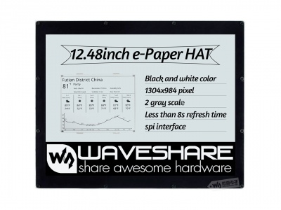
12.48inch e-Paper Module
| ||
| ||

Introduction
Feature
- Dimension: 12.48inch
- Outline dimension (raw panel):261.5mm × 211mm × 0.3mm
- Outline dimension (Acrylic case):280mm x 229.5mm
- Display size:252.976mm × 190.896mm
- Working voltage:3.3V/5V
- Interface:SPI
- Dot pitch:0.194mm × 0.194mm
- Resolution:1304 x 984
- Display color:Black, white
- Grey level:2
- Full refresh time :8s
- Refresh power : 26.4mW(typ.)
- Standby current :<0.01uA (almost none)
【Note】:
Refresh time:The data provided is experimental data, the actual time may be a little different.It is normal that the e-Paper blink when full updating.
Power:The power data is experimental data.
SPI Communication Timing

Since the ink screen only needs to be displayed, the data cable (MISO) sent from the machine and received by the host is hidden here.
- CS: Slave chip select, when CS is low, the chip is enabled
- DC: data/command control pin, write command when DC=0; write data when DC=1
- SCLK: SPI communication clock
- SDIN: SPI communication master sends, slave receives
- Timing: CPHL=0, CPOL=0 (SPI0)
【Remarks】For specific information about SPI, you can search for information online.
If the display is misaligned or the partitions are out of sync, try reducing the SPI rate.
How e-Paper display

As we know, this display uses the SPI interface, however, there are two FPC cables. In fact, the 12.48inch e-Paper is combined by four small e-Paper, therefore, to control the e-Paper, you should use four chip select pin.
- Update essence
It works as below:
We name the four areas as S2, M2, M1 and S1 respectively, in demo codes, we will send data to these four area in order.
The resolution of S2 and M1 are same 648*492, and the resolution of M2 and S1 are the same 656*492.
Combine the four display we get the resolution of 12.48inch e-Paper: 1304*984

- Control principle
They are four display indeed, therefore, we need to control four SPI salves:
Generally, the control pins of e-Paper are MOSI, SCLK, CS and DC
And power and reset pins: VCC, GND, RST
Because e-Paper will flash when updating, there is a busy pin:BUSY
To reduce pins, four displays use the same VCC, GND, MOSI and SCK pins. Every two displays use the same DC and RST pins.
Therefore, there are total 16 pins for controlling the e-Paper:
- Codes analysis
To control the e-Paper, you should first reset and initialize registers. And then transmit image data to e-Paper and update.
Here we show you how to transmit the image data:
We take Black-white or Red-white image as a monochrome bitmap. One byte stands for 8 pixels.
S2 and M1: There are 648 pixels per raw, It needs 648/8 = 81 bytes. One display has 492 column,totally have 81 * 492 = 39852 bytes. The same as the M2 and S1: They totally have 40344 per display。
Registers 0x13 and 0x10 are used to control Black-white image data and Red image data transmitting, here we take two-color display as example
| Color | 0x10 | 0x13 |
| White | 0xFF | 0x00 |
| Black | 0x00 | 0x00 |
| Red | 0xFF/0x00 | 0xFF |
void EPD_12in48_Display(const UBYTE *Image)
{
    int x,y;
    //S1 part 648*492
    EPD_S2_SendCommand(0x13);
    for(y = 0; y < 492; y++)
        for(x = 0; x < 81; x++) {
            EPD_S2_SendData(*(Image + (y*163 + x)));
        }

    //M2 part 656*492
    EPD_M2_SendCommand(0x13);
    for(y = 0; y < 492; y++)
        for(x = 81; x < 163; x++) {
            EPD_M2_SendData(*(Image+ (y*163) +x));
        }

    //S1 part 656*492
    EPD_S1_SendCommand(0x13);
    for(y = 492; y < 984; y++)
        for(x = 81; x < 163; x++) {
            EPD_S1_SendData(*(Image+ (y*163) +x));
        }

    //M1 part 648*492
    EPD_M1_SendCommand(0x13);
    for(y = 492; y < 984; y++)
        for(x = 0; x < 81; x++) {
            EPD_M1_SendData(*(Image+ (y*163) +x));
        }

    EPD_12in48_TurnOnDisplay();
}
We provide demo codes for four popular hardware platforms, Raspberry Pi, Arduino UNO, STM32 and the ESP32. The product you receive may be pre-assembled, you need to remove the back panel and connect your device like Raspberry Pi.
Preface
How to Install
Since it was assembled by us when you got the product, it has a base board, you need to take the screwdriver delivered to unscrew the screws on the back and put it into the main control.
- The Raspberry Pi, Arduino UNO, and ESP32 directly provide interface connections, and the specific control pins are introduced in the following sections.
- For STM32, the demo is based on the STM32F103ZET6 chip, which was tested using our Open103Z, and connected using the pin headers of the board.
Software Description
Raspberry Pi Programs
We provide two program drivers, C and Python.
It takes about 8S to brush a frame of a picture in C language and about 10s in Python. In addition to the basic refreshing effect, python codes also can catch the weather information:
- For the overseas version, we use weather data caught from https://www.msn.com/en-us/Weather/?day=1 webpage.
Arduino UNO
We provide a C program, and the .c suffix is changed to .cpp to be compatible with CPP.
Because the RAM of UNO is too small, 3x 23LC1024 chips are used onboard to expand the memory of UNO. You need to build a picture of the whole picture and initialize it. For black and white pictures, you need 1304/8*984=160392 pieces Bytes, and a 23LC1024 can only have a maximum size of 128K. For black and white red, it needs 160392*2 = 320784 bytes, so 3 chips are needed, so the display speed of the whole frame picture is very slow and is about 1 minute. to display a black-and-white image.
- The jumper cap needs to be connected to 5V.
STM32
We provide a C program.
- Since STM32F103ZET6 has no interface for direct use, it needs to be connected with the delivered Dupont cable. For the specific connection method, please refer to the pin connection diagram below. There are only some examples here because the STM32F103ZET6 cannot establish a complete image cache, only part of the screen demos.
ESP32
We provide a C program for the Arduino test program and an example that can be controlled using the web page.
- Arduino: It can be used according to the corresponding ESP32 chapters. ESP32 cannot create a 1304/8*984 cache, so it is refreshed differently, 4304/8*492 data is transmitted at one time, and black and white needs to be transmitted twice. Black and white red transmission 4 times. The refresh speed of black and white is about 8S, and the refresh speed of black and white is about 16S.
- Web page control: Due to my limited skills, I develop web pages while learning the front end. There may be some bugs in web page control, and you may not be able to complain, but the function can be completed in the end. The IP address will be displayed on the serial port. Under the same wifi, you can use the web page to open the IP address to control it, which will be described in detail in the subsequent chapters.
Raspberry Pi
Hardware Connection

The pins used can be found on schematic according to codes.

Enable SPI interface
- Open the Raspberry Pi terminal and input the following commands to enter the configuration interface:
sudo raspi-config
Select Interfacing Options -> SPI -> No to enable the SPI interface


- Reboot the Raspberry Pi:
sudo reboot
Libraries installation
- Install lg library:
#Open the Raspberry Pi and run the following commands:
wget https://github.com/joan2937/lg/archive/master.zip
unzip master.zip
cd lg-master
make
sudo make install
#For more details, you can refer to https://github.com/gpiozero/lg
- Install the gpiod library: (optional)
#Open the Raspberry Pi, and run the following commands:
sudo apt-get update
sudo apt install gpiod libgpiod-dev
- Install BCM2835 (optional):
#Open the Raspberry Pi terminal and run the following commands:
wget http://www.airspayce.com/mikem/bcm2835/bcm2835-1.71.tar.gz
tar zxvf bcm2835-1.71.tar.gz
cd bcm2835-1.71/
sudo ./configure && sudo make && sudo make check && sudo make install
#For more details, you can refer to:http://www.airspayce.com/mikem/bcm2835/
- Install wiringPi (optional):
#Open the Raspberry Pi terminal and run the following command
sudo apt-get install wiringpi
#For Raspberry Pi systems after May 2019 (earlier than before, you may not need to execute), you may need to upgrade:
wget https://project-downloads.drogon.net/wiringpi-latest.deb
sudo dpkg -i wiringpi-latest.deb
gpio -v
# Run gpio -v and version 2.52 will appear. If it does not appear, the installation is wrong

#Bullseye branch system use the following command:
git clone https://github.com/WiringPi/WiringPi
cd WiringPi
./build
gpio -v
# Run gpio -v and version 2.60 will appear. If it does not appear, it means that there is an installation error
Install Python Library
- Install function library:
sudo apt-get update
sudo apt-get install python3-pip
sudo apt-get install python3-pil
sudo apt-get install python3-numpy
sudo pip3 install spidev
sudo pip3 install cairosvg
sudo apt-get install libcairo2 libcairo2-dev
pip3 install beautifulsoup4
- Install python2:
sudo apt-get update
sudo apt-get install python-pip
sudo apt-get install python-pil
sudo apt-get install python-numpy
sudo pip install spidev
sudo pip install cairosvg
sudo apt-get install libcairo2 libcairo2-dev
pip install beautifulsoup4
Download
Open the terminal and run commands to download codes.
sudo apt-get install p7zip-full
wget https://files.waveshare.com/upload/9/9a/12.48inch_e-Paper_Module_Code_RPI.7z
7z x 12.48inch_e-Paper_Module_Code_RPI.7z -o./12.48inch_e-Paper_Module_Code
sudo chmod 777 -R 12.48inch_e-Paper_Module_Code
cd 12.48inch_e-Paper_Module_Code
Run codes
- C codes:
cd c
sudo nano examples/main.c
- Confirm the screen you use is black & white or black & white & red:
The demo for black & white:

- If you use the tree-color display, modify the file as below.

Press ctrl+x, and Y to save and exit, and execute the commands as shown below:
make clean
make
sudo ./epd
- Python codes:
cd python/examples
#Black&white screen:
sudo python3 epd_12in48_test.py
#Black&white&red screen:
sudo python3 epd_12in48B_test.py
Or
sudo python3 epd_12in48B_V2_test.py
- Python code for displaying weather:
Note: We have not found a free account for a weather API. Therefore, we are using Python web scraping to gather weather information from foreign sources.
cd python/examples
#Black&white screen runs:
sudo python3 Show_EN_Weather.py
#Black&white&red screen runs:
sudo python3 Show_EN_Weather.py B
#Or
sudo python3 Show_EN_Weather.py B_V2
#Help:
sudo python3 Show_EN_Weather.py help

Arduino
Hardware connection
You can directly insert the Arduino UNO into the PCB.
- Note: you need to connect the jumper cap to 5V.

About the pins used:

Run codes
- Download demo codes from the wiki and unzip them.
- Copy the 12in48 folder to the libraries directory which is under the installation directory of Arduino IDE. (The installation directory generally is C:\Program Files (x86)\Arduino\libraries)
- Open Arduino IDE software, choose Tool -> Board -> Arduino UNO:

- Click File -> Examples -> EPD12in48 to open demo code.

- If your e-Paper is a two-color version, use the epd12in48-demo, otherwise, use the epd12in48b-demo.
- Compile and download the codes to the board.


If you are using a black and white screen, select epd12in48-demo on the right.
If you are using a black, white, and red screen, select epd12in48b-demo on the right.
Finally, select the corresponding COM port, and then click Compile and Download.
- Note that the refresh process may take a long time. You can open the serial monitor to check the progress. Generally, it takes 1 minute for black and white screen, and 2 minutes for a black, white and red screen.
STM32
Preparation
The development board we use is Waveshare Open103Z. The project is developed based on STM32 HAL libraries.
Open 103Z
To assemble the Open32, you should connect the 2*8PIN header to the wires provided.

About the pins used, you can refer to the e-paper.ioc file (open STM32CUBEMX to see), as shown below:


Open the project (STM32\STM32-F103ZET6\MDK-ARM\e-paper.uvprojx), compile, and download it to the development board.
It requires about 10s for the two-color version and 20s for the three-color display.
ESP32
We provide two demos in the Arduino environment for development, the first needs to build the Arduino ESP32 environment, this can be a separate study in the ESP32 user manual, but for the sake of tutorial completeness, here can also be introduced again:
1. If your computer has not been installed Arduino IDE or the IDE version is old, it is recommended to download the latest IDE on Arduino's official website.
2. Download the Arduino-ESP32 support package: https://codeload.github.com/espressif/arduino-esp32/zip/master. Unzip it to Arduino IDE Hardware -> espressif -> esp32. (Note: if you don't have a folder in your installation directory, you can create one manually.)

3. Enter the tools folder, and run the get.exe file as administrator.
4. After installing, Copy the esp32-epd-12in48 folder of ESP32 demo codes to [Arduino IDE installation directory]/Hardware/espressif/esp32/libraries (Generally, its directory is C:\Program Files (x86)\Arduino\hardware\espressif\esp32\libraries.)

Hardware connection
Two demos are verified using the e-Paper ESP32 Driver Board, which can be plugged directly into the ESP32 interface on the driver board.

About the pins used, you can refer to schematic and codes

Arduino Example
Open Arduino IDE software, and find the examples on File -> Examples.

If you use a two-color e-Paper, choose the epd12in48-demo.
If you use a three-color e-Paper, use the epd12in48B-demo.
WiFi Example
ESP32 supports WiFi and can serve as a server and client, allowing us to program it to control an e-paper display via a web interface. This functionality has been implemented in the E-Paper ESP32 Driver Board. However, this may be difficult for some beginners. Therefore, we are resetting the approach here. there may be bugs that are not all discovered during testing. We hope you can point out any shortcomings so that we can strive to improve.
In the "wifi" directory under the esp32 directory, since it involves WiFi usage, you cannot directly use the example code. You need to modify the WiFi account and password in the program:
Open the "Web_App.cpp" file in the directory, and on lines 50 and 51, you will find the account and password. Modify them according to your credentials.
:
- Open wifi.ino file, compile and download it to your ESP32 board. Open the Serial monitor to query the IP address.

- Open the Chrome browser, and enter the web with the IP address.

The IP address is shown above and you can choose between 12.48-inch e-paper and 12.48-inch e-paper b which corresponds to the two-color e-Paper and three-color e-Paper respectively, choose it according to your screen.
- Select the display type, here we take 12.48inch e-Paper (two-color version) as an example:
- Click on the 12.48inch e-paper, the right side will show 6 functions, which can be achieved by drawing dots, first, boxes, circles, characters, and pictures, the home page will show the pixels of the e-Paper screen and the colors that can be displayed, pay attention to the color of the ink screen is to use BLACK, if white, nothing will show up:


- The corresponding coordination of display is as below:

- Draw points
- Click Draw Point, and the right side will pop up the following, there are 4 options: the coordinates of the corresponding point, color, and pixel point size. (Note that the coordinates do not exceed the maximum pixels of the image, otherwise it will not be displayed), after you have chosen, click anywhere to display the effect!

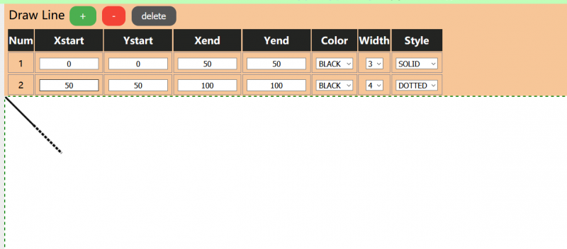
- Draw lines
- Click Draw Line, and the right side will pop up the following, there are 7 options: corresponding to the starting coordinates of the line (4), color, line width, solid dashed line. (Note that the coordinates do not exceed the maximum pixels of the image, otherwise it will not be displayed), If all are selected, click anywhere to display the effect!
- Draw Rectangle
- Click Draw Rectangle, and the right side will pop up the following, there are 7 options: corresponding to the starting coordinates of the box (4), color, line width, and whether the internal fill. (Note that the coordinates do not exceed the maximum pixels of the image, otherwise it will not be displayed), after you have chosen, click anywhere to display the effect!

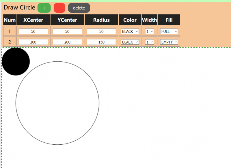
- Draw circle
- Click Draw Circle, the following will pop up on the right side, there are 6 options: the coordinates of the corresponding circle center, radius, color, and line width, and whether the interior is filled. (Note that the coordinates do not exceed the maximum pixels of the picture, otherwise it will not be displayed), all selected, click anywhere to display the effect!
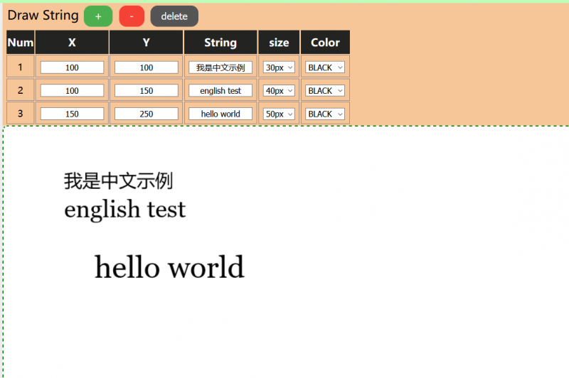
- Draw String
- Click Draw String, the following will pop up on the right side, there are 5 options: the coordinates of the left vertex of the corresponding character, the content of the character, the size of the font, the color. (Note that the coordinates do not exceed the maximum pixels of the image, otherwise it will not be displayed), are selected, click anywhere to display the effect!
- Display picture
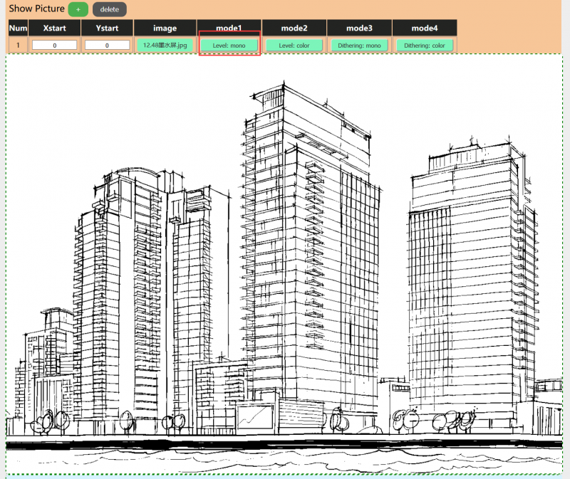
- Click Show Picture, and the right side will pop up the following, there are seven options: the coordinates of the left vertex of the corresponding picture, the picture displayed, four kinds of image processing algorithms, corresponding to black and white level algorithm, three-color color level algorithm, black and white dithering algorithm, three-color dithering algorithm (pay attention to the coordinates of the picture do not exceed the maximum number of pixels, or will not be displayed), are well chosen, click on any location to display the effect! Click Upload image, you can choose the local image, select the corresponding image, and click open.

- Draw the page to the bottom to check the original picture.

- Here, the corresponding algorithm is needed: Since a black and white screen is being used, only the mono-level algorithm and the mono-dithering algorithm are supported (the following attached images will display the effects of the images). If you click on the two red boxes, the popup warning will appear.

- Click Show Picture, and the right side will pop up the following, there are seven options: the coordinates of the left vertex of the corresponding picture, the picture displayed, four kinds of image processing algorithms, corresponding to black and white level algorithm, three-color color level algorithm, black and white dithering algorithm, three-color dithering algorithm (pay attention to the coordinates of the picture do not exceed the maximum number of pixels, or will not be displayed), are well chosen, click on any location to display the effect! Click Upload image, you can choose the local image, select the corresponding image, and click open.
- Upload Image
- Finally, click the upload image button on the left to upload the image, the black and white screen will display after waiting for 10s.


- You can open the Serial monitor of the IDE to check the debug message.

- You can also press the F12 button to open the debug console of the browser.


Resources
Document
Demo codes
Datasheet
Third-Party examples
- It is a "ESP-IDF component", you can drive the e-Paper with GFX and Fonts.
FAQ
Question about Software
{{{5}}}
{{{5}}}
{{{5}}}
1. First check whether the wiring is correct.
2. Check whether the spi is turned on and whether the parameters are configured correctly (spi baud rate, spi mode, and other parameters).
{{{5}}}
{{{5}}}
{{{5}}}
{{{5}}}
Question about Hardware
{{{5}}}
- The rated input voltage of the ink screen is 2.3~3.6V. If it is a 5V system, level conversion is required. In addition, the voltage should not be lower than 2.5V, so as not to affect the display effect of the e-paper screen.
- Device selection can use the model in the schematic diagram we provide or choose according to the data sheet.
{{{5}}}
{{{5}}}
- Check if SPI communication is normal.
- Confirm whether the BUSY pin is normally initialized to input mode.
- It may be that there is no normal reset, try to shorten the duration of the low level during reset (because the power-off switch is added to the drive circuit, the reset low level is too long, which will cause the drive board to power off and cause the reset to fail).
- If the busy function sends the 0x71 command, you can try to comment it out.
{{{5}}}
- 0.5mm pitch, 24Pin.
{{{5}}}
{{{5}}}
Question about Screen
- 【Working conditions】Temperature range: 0~50°C; Humidity range: 35%~65%RH.
- 【Storage conditions】Temperature range: below 30°C; Humidity range: below 55%RH; Maximum storage time: 6 months.
- 【Transportation conditions】Temperature range: -25~70°C; Maximum transportation time: 10 days.
- 【After unpacking】Temperature range: 20°C±5°C; Humidity range: 50±5%RH; Maximum storage time: Assemble within 72 hours.
{{{5}}}
- refresh mode
- Full refresh: The electronic ink screen will flicker several times during the refresh process (the number of flickers depends on the refresh time), and the flicker is to remove the afterimage to achieve the best display effect.
- Bureau brush: The electronic ink screen has no flickering effect during the refresh process. Users who use the partial brushing function note that after refreshing several times, a full brush operation should be performed to remove the residual image, otherwise the residual image problem will become more and more serious, or even damage the screen (currently only some black and white e-ink screens support partial brushing, please refer to product page description).
- refresh rate
- During use, it is recommended that customers set the refresh interval of the e-ink screen to at least 180 seconds (except for products that support the local brush function).
- During the standby process (that is, after the refresh operation), it is recommended that the customer set the e-ink screen to sleep mode, or power off (the power supply part of the ink screen can be disconnected with an analog switch) to reduce power consumption and prolong the life of the e-ink screen. (If some e-ink screens are powered on for a long time, the screen will be damaged beyond repair.)
- During the use of the three-color e-ink screen, it is recommended that customers update the display screen at least once every 24 hours (if the screen remains the same screen for a long time, the screen burn will be difficult to repair).
- Full refresh: The electronic ink screen will flicker several times during the refresh process (the number of flickers depends on the refresh time), and the flicker is to remove the afterimage to achieve the best display effect.
- Application
- The e-ink screen is recommended for indoor use. If it is used outdoors, it is necessary to avoid direct sunlight on the e-ink screen, and at the same time, take UV protection measures, because charged particles will dry out under strong light for a long time, resulting in loss of activity and failure to refresh. This situation is irreversible. When designing e-ink screen products, customers should pay attention to determining whether the use environment meets the requirements of the e-paper screen.
- The e-ink screen is recommended for indoor use. If it is used outdoors, it is necessary to avoid direct sunlight on the e-ink screen, and at the same time, take UV protection measures, because charged particles will dry out under strong light for a long time, resulting in loss of activity and failure to refresh. This situation is irreversible. When designing e-ink screen products, customers should pay attention to determining whether the use environment meets the requirements of the e-paper screen.
{{{5}}}
{{{5}}}
{{{5}}}
{{{5}}}
Insufficient or unstable power supply leads to data loss.
The data cable is too long to cause data loss, the extension cable should not exceed 20cm.
{{{5}}}
Different batches of e-paper diaphragms and electrophoretic matrices require different voltage values when driving the display due to materials, manufacturing processes, etc. The waveform of the e-ink screen is reflected in the relationship between grayscale, voltage, and temperature. Generally speaking, after each batch of electrophoresis matrix is generated, there will be a corresponding waveform file in the form of a .wbf file. The film manufacturer will provide the waveform file and electrophoresis matrix to the manufacturer of the electronic paper screen, and then the manufacturer of the electronic paper screen integrates the protection board, substrate, and driver and then provides it to customers; if the waveform file does not correspond to the screen, it is likely that the display cannot be displayed or the display effect is unsatisfactory. Generally, the waveform file has OTP built into the driver IC of the ink screen when leaving the factory, and some programs we provide also call external waveform files to drive the e-ink screen.
{{{5}}}
{{{5}}}
{{{5}}}
{{{5}}}
Support
If you require technical support, please go to the Support page and open a ticket.