
RP2350-ETH-8DI-8RO
Overview
| ||

Introduction
RP2350-ETH-8DI-8RO is an industrial-grade 8-channel network relay based on RP2350B microcontroller and supports RS485, Ethernet port and other peripheral interfaces. It features built-in power isolation and optocoupler isolation and other protection circuits, which is safe, stable and more reliable.
Features
- RP2350B microcontroller chip officially designed by Raspberry Pi
- Unique dual-core and dual-architecture design, equipped with dual-core ARM Cortex-M33 processor and dual-core Hazard3 RISC-V processor, flexible clock running up to 150 MHz, supporting flexible switching between the two architectures
- Built-in 520KB of SRAM and 16MB of on-chip Flash
- Type-C port, easier to use
- High quality relay, contact rating: ≤10A 250V AC or ≤10A 30V DC
- The digital inputs feature bidirectional optocoupler isolation, supporting both passive and active switch inputs. The relay outputs can be controlled via a switch interlock (linkage) mode
- Onboard isolated RS485 interface, for connecting to various RS485 Modbus industrial modules or sensors
- Onboard pin header, allowing access to other devices
- Onboard power supply screw terminal, supports 7~36V wide voltage input, suitable for industrial applications
- Onboard RTC clock chip, supports timing tasks
- Onboard W5500 Ethernet chip, extending 10/100Mbps network connectivity via SPI interface
- PoE network port version supports external PoE module for Power over Ethernet (IEEE 802.3af compliant)
- Onboard optocoupler isolation to prevent interference with control chip from external high-voltage circuit connected to the relay
- Onboard digital isolation to avoid external signal interference with the control chip
- Onboard integrated power isolation, providing stable isolation voltage, no extra power supply required for the isolated terminal
- Onboard TF card slot, supporting external TF card storage for pictures or files
- Built-in buzzer, RGB colorful LED, power supply and RS485 TX/RX indicators for monitoring the operating status of the module
- Rail-mounted ABS protective enclosure, easy to install, safe to use
- USB1.1 host and slave device support
- Low-power sleep and dormant modes
- Drag-and-drop programming via USB mass storage
- 15 × multi-functional GPIO pins
- 2 × SPI, 2 × I2C, 2 × UART, 8 × 12-bit ADC and 12 × controllable PWM channels
- Accurate clock and timer on-chip
- Temperature sensor
- On-chip accelerated floating-point library
- 12 × Programmable I/O (PIO) state machines for custom peripheral support
Pinout Definition


Dimensions

Electrical and Relay Safety Instructions
- This product must be operated by professional electricians or qualified personnel. During use, ensure electrical safety, leakage protection, and proper insulation.
- Before installing, maintaining, or replacing the relay device, always turn off the power and unplug the device.
- Do not attempt to disassemble the relay device to avoid damage or the risk of electric shock.
- Properly install and place the relay device. Do not use it in humid, overheated, flammable, or explosive environments to prevent accidents caused by improper installation or use.
1. Load Matching
- Ensure the relay's rated voltage and current match the load. Do not exceed the rated capacity.
- For inductive loads (motors, coils, lamps, etc.), the starting current may be much higher than the rated current. Choose a relay with sufficient current margin.
2. Short Circuit and Overcurrent Protection
- Install a fuse or circuit breaker in the relay circuit to prevent damage due to short circuits or accidental overcurrent.
- Ensure the load circuit has no short circuits during wiring, and select protection components with appropriate current ratings if necessary.
3. Arc and Switching Protection
- Relay switching generates arcs, which can cause contact wear or welding.
- For inductive loads, it is recommended to use RC snubber circuits or varistors for arc suppression.
4. Installation Environment
- Do not use the relay in humid, high-temperature, flammable, explosive, or dusty environments.
- Install the relay securely to avoid vibrations or shocks that may cause misoperation or damage.
5. Power-Off Operation
- Always cut off power before maintenance, wiring, or replacing the relay to ensure personnel and device safety.
- Latching relays are only powered when changing state. Avoid strong vibrations or strong magnetic fields while the relay is unpowered.
6. Status Confirmation
- After powering on, confirm or reset the relay status as needed to prevent abnormal operation caused by transportation, installation, or external disturbances.
- Avoid power interruption during relay operation to prevent uncertain status or contact damage.
7. Regular Inspection
- Periodically inspect relay contacts, terminals, and insulation to ensure proper operation.
- If abnormal heating, odor, or burn marks are detected, immediately cut off power and replace the relay.
Pico Getting Started
Firmware Download
- MicroPython Firmware Download

- C_Blink Firmware Download

Basic Introduction
MicroPython Series
Install Thonny IDE
To facilitate the development of Pico/Pico2 boards with MicroPython on a computer, it is recommended to download the Thonny IDE
- Download Thonny IDE and follow the steps to install, the installation packages are all Windows versions, please refer to Thonny's official website for other versions
- After installation, configure the language and motherboard environment for the first use. Since we are using Pico/Pico2, pay attention to selecting the Raspberry Pi option for the motherboard environment

- Configure MicroPython environment and choose Pico/Pico2 port
- Connect Pico/Pico2 to your computer first, and in the lower right corner of Thonny left-click on the configuration environment option --> select Configure interpreter
- In the pop-up window, select MicroPython (Raspberry Pi Pico), and choose the corresponding port


Flash Firmware
- Click OK to return to the Thonny main interface, download the corresponding firmware library and flash it to the device, and then click the Stop button to display the current environment in the Shell window
- Note: For the Pico series board, you can directly use the firmware provided by MicroPython official. For the RP series board, please use the firmware provided below or in the program package.
- Steps to compile the latest firmware
- How to download the firmware library for Pico/Pico2 in windows: After holding down the BOOT button and connecting to the computer, release the BOOT button, a removable disk will appear on the computer, copy the firmware library into it
- How to download the firmware library for RP2040/RP2350 in windows: After connecting to the computer, press the BOOT key and the RESET key at the same time, release the RESET key first and then release the BOOT key, a removable disk will appear on the computer, copy the firmware library into it (you can also use the Pico/Pico2 method)

MicroPython Series Tutorials
【MicroPython】machine.Pin class function details
【MicroPython】machine.PWM class function details
【MicroPython】machine.ADC class function details
【MicroPython】machine.UART class function details
【MicroPython】machine.I2C class function details
【MicroPython】machine.SPI class function details
【MicroPython】rp2.StateMachine class function details
C/C++ Series
For C/C++, it is recommended to use Pico VSCode for development. This is a Microsoft Visual Studio Code extension designed to make it easier for you to create, develop, and debug projects for the Raspberry Pi Pico series development boards. No matter if you are a beginner or an experienced professional, this tool can assist you in developing Pico with confidence and ease. Here's how to install and use the extension.
- Official website tutorial: https://www.raspberrypi.com/news/pico-vscode-extension/
- This tutorial is suitable for Raspberry Pi Pico, Pico2 and the RP2040 and RP2350 series development boards developed by Waveshare
- The development environment defaults to Windows11. For other environments, please refer to the official tutorial for installation
Install VSCode
-
First, click to download pico-vscode package, unzip and open the package, double-click to install VSCode

Note: If vscode is installed, check if the version is v1.87.0 or later


Install Extension
-
Click Extensions and select Install from VSIX

-
Select the package with the vsix suffix and click Install

-
Then vscode will automatically install raspberry-pi-pico and its dependency extensions, you can click Refresh to check the installation progress

-
The text in the right lower corner shows that the installation is complete. Close VSCode


Configure Extension
-
Open directory C:\Users\username and copy the entire .pico-sdk to that directory

-
The copy is completed

-
Open vscode and configure the paths for the Raspberry Pi Pico extensions

The configuration is as follows:Cmake Path: ${HOME}/.pico-sdk/cmake/v3.28.6/bin/cmake.exe Git Path: ${HOME}/.pico-sdk/git/cmd/git.exe Ninja Path: ${HOME}/.pico-sdk/ninja/v1.12.1/ninja.exe Python3 Path: ${HOME}/.pico-sdk/python/3.12.1/python.exe


New Project
-
The configuration is complete, create a new project, enter the project name, select the path, and click Create to create the project
To test the official example, you can click on the Example next to the project name to select
-
The project is created successfully


Compile Project
-
Select the SDK version

-
Select Yes for advanced configuration

-
Choose the toolchain, 13.2.Rel1 is applicable for ARM cores, RISCV.13.3 is applicable for RISCV cores. You can select either based on your requirements

-
Select Default for CMake version (the path configured earlier)

-
Select Default for Ninja version

-
Select the development board

-
Click Compile to compile

-
The .uf2 format file is successfully compiled


Flash Firmware
Here are two methods for flashing firmware
-
Flash firmware using the pico-vscode plugin
Connect the development board to the computer, click Run to flash the firmware directly
-
Flash the firmware manually
1. Press and hold the Boot button
2. Connect the development board to the computer
3. Then the computer will recognize the development board as a USB device.
4. Copy the .uf2 file to the USB drive, and the device will automatically restart, indicating successful program flashing.

Import Project
-
Select the project directory and import the project

- The Cmake file of the imported project cannot have Chinese (including comments), otherwise the import may fail
-
To import your own project, you need to add a line of code to the Cmake file to switch between pico and pico2 normally, otherwise even if pico2 is selected, the compiled firmware will still be suitable for pico

set(PICO_BOARD pico CACHE STRING "Board type")


Update Extension
-
The extension version in the offline package is 0.15.2, and you can also choose to update to the latest version after the installation is complete


Arduino IDE Series
Install Arduino IDE
-
First, go to Arduino official website to download the installation package of the Arduino IDE.

-
Here, you can select Just Download.

-
Once the download is complete, click Install.

Notice: During the installation process, it will prompt you to install the driver, just click Install


Arduino IDE Interface
-
After the first installation, when you open the Arduino IDE, it will be in English. You can switch to other languages in File --> Preferences, or continue using the English interface.

-
In the Language field, select the language you want to switch to, and click OK.


Install Arduino-Pico Core in Arduino IDE
-
Open the Arduino IDE, click on the file in the top left corner, and select Preferences

-
Add the following link to the attached board manager URL, and then click OK
This link already includes board versions such as RP2040 and RP2350. Please visit arduino-pico for the latest version fileshttps://github.com/earlephilhower/arduino-pico/releases/download/4.5.2/package_rp2040_index.json

Note: If you already have an ESP32 board URL, you can use a comma to separate the URLs as follows:https://dl.espressif.com/dl/package_esp32_index.json,https://github.com/earlephilhower/arduino-pico/releases/download/4.5.2/package_rp2040_index.json
-
Click Tools > Development Board > Board Manager > Search pico, as my computer has already been installed, it shows that it is installed

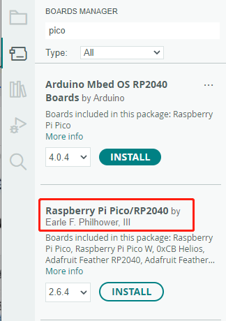


Upload Demo at the First Time
-
Press and hold the BOOTSET button on the Pico board, connect the pico to the USB port of the computer via the Micro USB cable, and release the button after the computer recognizes a removable hard disk (RPI-RP2).

- Download the program and open D1-LED.ino under the arduino\PWM\D1-LED path
-
Click Tools --> Port, remember the existing COM, do not click this COM (the COM displayed is different on different computers, remember the COM on your own computer)

-
Connect the driver board to the computer using a USB cable. Then, go to Tools > Port. For the first connection, select uf2 Board. After uploading, when you connect again, an additional COM port will appear

-
Click Tools > Development Board > Raspberry Pi Pico > Corresponding models (Raspberry Pi Pico, Raspberry Pi Pico 2, etc.)


- After setting it up, click the right arrow to upload the program


- If issues arise during this period, and if you need to reinstall or update the Arduino IDE version, it is necessary to uninstall the Arduino IDE completely. After uninstalling the software, you need to manually delete all contents within the C:\Users\[name]\AppData\Local\Arduino15 folder (you need to show hidden files to see this folder). Then, proceed with a fresh installation.
Open Source Demos
MircoPython video demo (github)
MicroPython firmware/Blink demos (C)
Raspberry Pi official C/C++ demo (github)
Raspberry Pi official MicroPython demo (github)
Arduino official C/C++ demo (github)
Demo
C/C++ Demo
01_RS485
Demo description
- This example implements the control of 8 relay switches via RS485 and 8DI digital inputs
Code analysis
- Relay_Control(): This function mainly executes the corresponding relay control operation and outputs the corresponding status prompt information according to the array index passed through the parameters
- Parameter analysis
uint8_t index: In themainfunction, the program will parse the received RS485 data and match it with the preset control command array. When a match is found, theRelay_Controlfunction is called, and the index position of the matching command in the array is passed viaindexparameter
- Logical flow
- Use the
if elsestatement to perform different operations based on the value ofindex:- In the case of
index < 8, that is, for theCH1~CH6commands, theDEV_Digital_Writefunction is used to switch the level status of the corresponding GPIO pin (such asRELAY1_PIN, etc.), and at the same time, the correspondingrelay_statusarray element is updated to record the change of the relay status, and the corresponding on or off prompt information is output according to the final state of the relay. Finally, in themainfunction, theBeepfunction is called to control the buzzer. - For the case of
index = 8, i.e., for theALL_ONcommand, all GPIO pins (corresponding to 8 channel relays) are set to high level (on state). Using thememsetfunction, all elements of therelay_statusarray are set to 1, indicating that all relays are turned on. A message indicating that all relays are turned on is then output. Finally, in themainfunction, theBeepfunction is called to control the buzzer. - For the case of
index = 9, i.e., for theALL_OFFcommand, all GPIO pins (corresponding to 8 channel relays) will be set to low level (off state). Using thememsetfunction, all elements of therelay_statusarray will be set to 0, indicating that all relays are off. A message indicating that all relays are off will be output. Finally, in themainfunction, theBeepfunction will be called to control the buzzer. - If the value of
indexdoes not match the above commands, the prompt message of receiving non-command data will be output
- In the case of
- Use the
- Parameter analysis
- gpio_irq_handler(): The function controls relay switches through IO interrupts, with digital interfaces DI1~DI8 corresponding to relays CH1~CH8. For example, when the digital interface DI1 is low, the relay CH1 is on, and when the digital interface DI1 is high, the corresponding relay CH1 is off
RS485 Control
- Jump to RS485 Control Tutorial
02_MQTT
Demo description
- This example implements network connection through an Ethernet interface and achieves remote control of 8 relays via the MQTT communication protocol
Precautions
- Devices need to be created in Waveshare Cloud
- MQTT related parameters in the program need to be modified
Code analysis
- Function description
ConnectNetwork(): Connect to the network via Ethernet portMQTTClientInit(): Initialize MQTTMQTTConnect(): Connect to MQTT serverMQTTSubscribe(): Subscribe to MQTT topicMQTTPublish(): Publish MQTT message
- Parameter description
- MQTT parameters
MQTT_CLIENT_ID: Client IDMQTT_USERNAME: UsernameMQTT_PASSWORD: PasswordMQTT_SUBSCRIBE_TOPIC: Name of the subscribed topicMQTT_PUBLISH_TOPIC: Name of the published topic
- Network connection parameters
g_net_info.mac: MAC addressg_net_info.ip: IP addressg_net_info.sn: Subnet maskg_net_info.gw: Gatewayg_net_info.dns: DNS server
- MQTT parameters
- Logical flow
- Device Initialization: Initialize the SPI interface of MQTT and Ethernet ports, call
ConnectNetwork(),MQTTConnect()to connect to the network and MQTT server, and callMQTTSubscribe()to subscribe to MQTT topics - Control relay switch: Wait for MQTT messages in the main loop. When it is determined that the received MQTT message
g_mqtt_client.msg.payloadis not empty, parse the MQTT message and control the corresponding relay switch - Send relay status: In order to determine whether the relay switch operation is successful from the server, the development board will call
MQTTPublish()to send the latest relay status to the server after controlling the relay switch
- Device Initialization: Initialize the SPI interface of MQTT and Ethernet ports, call
MicroPython Demo
01_RS485
Demo description
- This example implements the control of 8 relay switches via RS485 and 8DI digital inputs
Code analysis
- relay_control(): This function mainly executes the corresponding relay control operation and outputs the corresponding status prompt information according to the array index passed through the parameters
- Parameter analysis
index: In themainfunction, the program will parse the received RS485 data and match it with the preset control command array. When a match is found, therelay_controlfunction is called, and the index position of the matching command in the array is passed viaindexparameter
- Logical flow
- Use the
if elsestatement to perform different operations based on the value ofindex:- In the case of
index < 8, that is, for theCH1~CH6commands, therelays[index].valuefunction is used to switch the level status of the corresponding GPIO pin, and at the same time, the correspondingrelay_statusarray element is updated to record the change of the relay status, and the corresponding on or off prompt information is output according to the final state of the relay. Finally, thebeepfunction is called to control the buzzer. - For the case of
index = 8, i.e., for theALL_ONcommand, all GPIO pins (corresponding to 8 channel relays) are set to high level (on state), and all elements of therelay_statusarray are set to 1 through theforloop, indicating that all relays are turned on. A message indicating that all relays are turned on is then output. Finally, thebeepfunction is called to control the buzzer. - For the case of
index = 9, i.e., for theALL_OFFcommand, all GPIO pins (corresponding to 8 channel relays) will be set to low level (off state). Using theforloop, all elements of therelay_statusarray will be set to 0, indicating that all relays are off. A message indicating that all relays are off will be output. Finally, thebeepfunction will be called to control the buzzer. - If the value of
indexdoes not match the above commands, the prompt message of receiving non-command data will be output
- In the case of
- Use the
- Parameter analysis
- gpio_irq_handler(): The function controls relay switches through IO interrupts, with digital interfaces DI1~DI8 corresponding to relays CH1~CH8. For example, when the digital interface DI1 is low, the relay CH1 is on, and when the digital interface DI1 is high, the corresponding relay CH1 is off
RS485 Control
- Jump to RS485 Control Tutorial
02_MQTT
Demo description
- This example implements network connection through an Ethernet interface and achieves remote control of 8 relays via the MQTT communication protocol
Precautions
- Devices need to be created in Waveshare Cloud
- MQTT related parameters in the program need to be modified
Code analysis
- Function description
ethernet_init(): Connect to the network via Ethernet portmqtt_connect(): Connect to MQTT servermqtt_subscribe(): Subscribe to MQTT topicmqtt_publish(): Publish MQTT message
- Parameter description
- MQTT parameters
MQTT_SERVER: Server IPMQTT_PORT: Server port numberMQTT_CLIENT_ID: Client IDMQTT_USERNAME: UsernameMQTT_PASSWORD: PasswordMQTT_SUBSCRIBE_TOPIC: Name of the subscribed topicMQTT_PUBLISH_TOPIC: Name of the published topic
- MQTT parameters
- Logical flow
- Device Initialization: Initialize W5500 and MQTT, call
ethernet_init(),mqtt_connect()to connect to the network and MQTT server, and callmqtt_subscribe()to subscribe to MQTT topics - Control relay switch: Set the MQTT receive callback function through
client.set_callback(), wait for the MQTT message in the main loop, callmqtt_recv_callback()after judging the received MQTT message, parse the MQTT message and control the corresponding relay switch - Send relay status: In order to determine whether the relay switch operation is successful from the server, the development board will call
mqtt_publish()to send the latest relay status to the server after controlling the relay switch
- Device Initialization: Initialize W5500 and MQTT, call
External Expansions
RS485 Extended Relay Channels
- Use Modbus RTU Relay to extend 6-ch relay
- Connect Modbus RTU Relay to the RS485 port of RP2350-ETH-8DI-8RO
- The demo will turn on CH1~CH6 of Modbus-RTU-Relay one by one, and then turn them off one by one
Resources
Supporting Resources
Demo
Datasheets
Official Resources
Raspberry Pi Official Documents
- Get Started with MicroPython on Raspberry Pi Pico
- Raspberry Pi related books download
- Pico2 Schematic diagram
- Pico2 Pinout definition
- Pico2 Getting Started
- Pico2 C SDK User Manual
- Pico2 Python SDK User Manual
- Pico2 Datasheet
- RP2350 Datasheet
- RP2350 Hardware Design Reference Manual
Raspberry Pi Open Source Demos
Development Software
- Thonny Python IDE (Windows version V3.3.3)
- Pico environment building related software
- pico-vscode package
- SSCOM
- USB-CAN-A_TOOL
FAQ
Please move the jumper cap to 120R and try again. Some RS485 devices require a 120R resistor to be connected in series
Support
Technical Support
If you need technical support or have any feedback/review, please click the Submit Now button to submit a ticket, Our support team will check and reply to you within 1 to 2 working days. Please be patient as we make every effort to help you to resolve the issue.
Working Time: 9 AM - 6 PM GMT+8 (Monday to Friday)