
RP2040-Zero
| ||
| ||


Overview
RP2040-Zero, A Low-Cost, High-Performance Pico-Like MCU Board Based On Raspberry Pi Microcontroller RP2040.
Specification
- RP2040 microcontroller chip designed by Raspberry Pi in the United Kingdom.
- Dual-core Arm Cortex M0+ processor, flexible clock running up to 133 MHz.
- 264KB of SRAM, and 2MB of on-board Flash memory.
- USB-C connector, keeps it up to date, easier to use.
- The castellated module allows soldering direct to carrier boards.
- USB 1.1 with device and host support.
- Low-power sleep and dormant modes.
- Drag-and-drop programming using mass storage over USB.
- 29 × multi-function GPIO pins (20× via edge pinout, others via solder points).
- 2 × SPI, 2 × I2C, 2 × UART, 4 × 12-bit ADC, 16 × controllable PWM channels.
- Accurate clock and timer on-chip.
- Temperature sensor.
- Accelerated floating-point libraries on-chip.
- 8 × Programmable I/O (PIO) state machines for custom peripheral support.
Pinouts

Dimension

Anti-piracy statement
Many unscrupulous merchants in the market maliciously copy Waveshare products, the general characteristics of these unscrupulous merchants are:
- Copying web page descriptions, product pictures, and product information.
- The use of poor components, the light operation is not stable, and may appear short circuit, equipment burned, and other phenomena (to avoid your property losses, please beware of piracy).
- Do not pay attention to product quality, no ability to deal with after-sales. (We not only produce excellent quality boards but also provide a strong after-sales team to protect your products and works).
- Recognize Waveshare genuine products, we have the following characteristics in terms of configuration and appearance:
- With Waveshare LOGO (certificate).
- Immersion gold process (only some models, see product description).
Pico Quick Start
Download Firmware
- MicroPython Firmware Download

- C_Blink Firmware Download

Video Tutorial
- Pico Tutorial I - Basic Introduction
- Pico Tutorial II - GPIO
- Pico Tutorial III - PWM
- Pico Tutorial IV - ADC
- Pico Tutorial V - UART
- Pico Tutorial VI - To be continued...
MicroPython Series
- 【MicroPython】 machine.Pin Function
- 【MicroPython】 machine.PWM Function
- 【MicroPython】 machine.ADC Function
- 【MicroPython】 machine.UART Function
- 【MicroPython】 machine.I2C Function
- 【MicroPython】 machine.SPI Function
- 【MicroPython】 rp2.StateMachine
C/C++ Series
Arduino IDE Series
Install Arduino IDE
-
Download the Arduino IDE installation package from Arduino website.

-
Just click on "JUST DOWNLOAD".

-
Click to install after downloading.
-
Note: You will be prompted to install the driver during the installation process, we can click Install.


Install Arduino-Pico Core on Arduino IDE
-
Open Arduino IDE, click the File on the left corner and choose "Preferences".

-
Add the following link in the additional development board manager URL, then click OK.
https://github.com/earlephilhower/arduino-pico/releases/download/global/package_rp2040_index.json

Note: If you already have the ESP8266 board URL, you can separate the URLs with commas like this:https://dl.espressif.com/dl/package_esp32_index.json,https://github.com/earlephilhower/arduino-pico/releases/download/global/package_rp2040_index.json
-
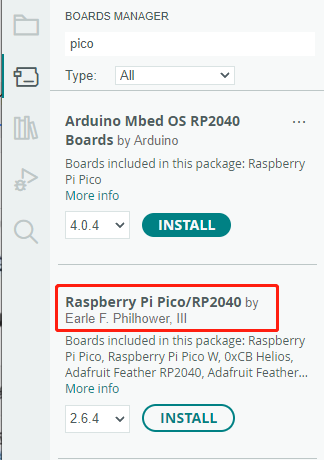
Click on Tools -> Dev Board -> Dev Board Manager -> Search for pico, it shows installed since my computer has already installed it.


Upload Demo At the First Time
-
Press and hold the BOOTSET button on the Pico board, connect the Pico to the USB port of the computer via the Micro USB cable, and release the button when the computer recognizes a removable hard drive (RPI-RP2).

- Download the demo, open arduino\PWM\D1-LED path under the D1-LED.ino.
-
Click Tools -> Port, remember the existing COM, do not need to click this COM (different computers show different COM, remember the existing COM on your computer).

-
Connect the driver board to the computer with a USB cable, then click Tools -> Ports, select uf2 Board for the first connection, and after the upload is complete, connecting again will result in an additional COM port.

-
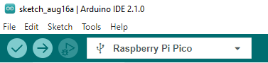
Click Tool -> Dev Board -> Raspberry Pi Pico/RP2040 -> Raspberry Pi Pico.

-
After setting, click the right arrow to upload.
- If you encounter problems during the period, you need to reinstall or replace the Arduino IDE version, uninstall the Arduino IDE needs to be uninstalled cleanly, after uninstalling the software you need to manually delete all the contents of the folder C:\Users\[name]\AppData\Local\Arduino15 (you need to show the hidden files in order to see it) and then reinstall.


Open Source Demo
- MicroPython Demo (GitHub)
- MicroPython Firmware/Blink Demo (C)
- Official Raspberry Pi C/C++ Demo
- Official Raspberry Pi MicroPython Demo
- Arduino Official C/C++ Demo
Resource
Example Demo
Official Document
Pico W
Firmware
Pico
User Manual
Schematic & Datasheet
Related Books
Raspberry Pi Open-source Demo
Development Software
Documents
Demo Codes
- Demo codes for Raspberry-Pi-Pico-Basic-Kit
- Demo codes for Raspberry Pi Pico Sensor Kit
- WS2812B Test Codes
FAQ
Debugging is not possible. You can program on a board that can be debugged and then directly burn the firmware into the RP2040 Zero.
{{{5}}}
The Bootrom of RP2040 provides a standard USB bootloader that identifies as a writable drive for copying code onto the RP2040 using UF2 files. UF2 files copied onto the drive are downloaded and written into Flash or RAM, and the device is automatically restarted, enabling code download and execution on the RP2040 using just a USB connection.
Any type of file can be written to the USB drive from the host, but typically these files are not stored—they appear this way due to caching on the host side. Only when a UF2 file is written to the device is special content recognized, and the data is written to the specified location in RAM or Flash. After downloading the complete and valid UF2 file, the RP2040 will automatically reboot to run the newly downloaded code.
UF2 files aren't stored; they are burned into designated locations based on the corresponding file format. For specific file formats, refer to the open-source project by Microsoft at https://github.com/microsoft/uf2.
{{{5}}}
Press RESET first, then press BOOT; release RESET first, then release BOOT to enter programming mode. You can drag and drop or copy the firmware into this mode for flashing.
{{{5}}}
The VSYS pin of the RP2040 is connected to the VUSB pin directly in RP2040-zero (named Pin23 ), If you want to connect the battery directly to the VSYS pin, you need to add a diode to avoid backflow. You can also directly connect the battery to Pin 21 (the 3V3) of the RP2040-zero if the voltage of the battery is 3.3V.
RP2040 zero itself has no battery protection function, you need to ensure that your battery will not be overcharged or over-discharged, causing safety accidents.
{{{5}}}
This board doesn't pin out the SWD pins.
{{{5}}}
Just use an OTG adapter like this or use a C2C cable:

{{{5}}}

Please check this:

{{{5}}}
If you do not use USB for power supply, you can use the 5V pin for power supply:

{{{5}}}
Support
Technical Support
If you need technical support or have any feedback/review, please click the Submit Now button to submit a ticket, Our support team will check and reply to you within 1 to 2 working days. Please be patient as we make every effort to help you to resolve the issue.
Working Time: 9 AM - 6 AM GMT+8 (Monday to Friday)