
Pico RGB LED
| ||

Overview
The Pico-RGB-LED is an LED matrix module designed for Raspberry Pi Pico, which has 160 (16 × 10) RGB full-color external-controlled constant current integrated LEDs, with embedded quality controller IC and LED chip. It is small in size, uses very few peripheral components, and presents a clean-looking front panel. Controlled by a Raspberry Pi Pico, this LED panel is programable for a high-level, colorful matrix display.
Feature
- Standard Raspberry Pi Pico header, supports Raspberry Pi Pico series.
- 160 RGB LEDs arranged in a 16 × 10 grid, multiple IO selection.
- Right-angled 2.54mm pitch male pin header on the bottom, for easy extension.
- 0807 colorful LEDs, integrating quality single wire cascading constant current driver IC and quality RGB LED chip, aka external-controlled constant *current integrated LEDs.
- Embedded controller IC, with features like high reliability, high anti-interference performance, high constant current accuracy, and low power consumption.
- Integrated quality LED chip, with high consistent brightness and pure white light effect, lower light degradation.
Specifications
- Operating voltage: 5V
- Communication: Single wire return to zero code
- Color depth: 24-bit (each 8-bit of RGB)
- Data rate: 800Kbps
- Brightness: adjustable 256 level
- Pixels: 16 x 10 pixels
- Dimensions: 54.00 x 26.00mm
Pinout

Dimension

About the RGB LED
Lamp bead used single communication way, with the method of zero code signal. After the chip is powered on and reset, it receives the data from the DIN end. After receiving enough 24 bits, the DO port begins to forward data for the next chip to provide input data. Before forwarding, the DO port is lowered. At this time, the lamp will not receive new data, the built-in RGB chip according to the received 24-bit data after the different duty cycle signal, show different brightness. If the DIN input signal is a RESET signal, the chip will send the received data to display, the chip will receive new data after the end of the signal, after receiving the starting 24-bit data, data will be forwarded through the DO port before the lamp does not receive the RESET code, the RGB brightness remains unchanged. When the low-level RESET code above 200us is received, the RGB chip inside the lamp bead will show different brightness according to the different duty cycle signals generated after the 24-bit data just received.
Data Transmition

Note: D1 is the data sent from MCU and D2, D3, D4 are the data automatically shaped and forwarded by cascaded circuits.
24-bit data structure

Note: Data in high bits are sent first and follow the RGB order.
Timing

| T0H | 0 code, time of High signal | 0.35µs | ±150ns |
| T1H | 1 code, time of High signal | 1.36µs | ±150ns |
| T0L | 0 code, time of Low signal | 1.36µs | ±150ns |
| T1L | 1 code, time of Low signal | 0.35µs | ±150ns |
| RES | RESET code | 50µs | \ |
Notice
- The product in RGB full light (24 for 1), will lead to the lamp bead surface temperature being too high, it is strictly prohibited to feel the temperature by hand.
- The current of this product is close to 2.5a when RGB is fully lit. It is recommended to use A power supply of 5V,3A, or more.
- Since the USB output current of the computer is low, we set the brightness data at RGB555, even if the full light is only about 300mA.
- Also do not set the current too low, if your brightness data is less than 4 bits, part of the light will not be bright.
Hardware Connection
Please take care of the direction when you connect Pico, an USB port is printed to indicate. You can also check the pin of Pico and the LCD board when connecting.
You can connect the display according to the table.
| RGB LED | Pico | Description |
| VCC | VBUS | Power Input |
| GND | GND | GND |
| DIN | GP6 | Data input |
| DIN | GP7 | Data input |
| DIN | GP22 | Data input |
| DOUT | \ | Data output |
Connection

Setup Environment
Please refer to Raspberry Pi's guide: https://www.raspberrypi.org/documentation/pico/getting-started/
Download Demo codes
sudo apt-get install p7zip-full
cd ~
sudo wget  https://files.waveshare.com/upload/2/28/Pico-RGB-LED_code.7z
7z x Pico-RGB-LED_code.7z -o./Pico-RGB-LED_code
cd ~/Pico-RGB-LED_code
cd c/build/
Run the Demo codes
This guide is based on Raspberry Pi.
C Examples
Open a terminal and enter the directory of C codes:
cd ~/Pico-RGB-LED_code/c/
Create a build folder and add SDK:
For example, if the path of SDK is ../../pico-sdk
Then you should create a build and add the path like these:
mkdir build
cd build
export PICO_SDK_PATH=../../pico-sdk
Run cmake.. command to generate the Makefile file:
cmake ..
Run make command to build.
make -j9
After the compilation is complete, the uf2 file will be generated. Press and hold the button on the Pico board, connect the Pico to the USB port of the Raspberry Pi through the Micro USB cable, and release the button. After connecting, the Raspberry Pi will automatically recognize a removable disk (RPI-RP2) and copy the main.uf2 file in the build folder to the recognized removable disk (RPI-RP2).
cp main.uf2 /media/pi/RPI-RP2/
Python Codes
Use in Windows
- 1. Press and hold the BOOTSET button on the Pico board, connect the Pico to the USB port of the computer through the Micro USB cable, and release the button after the computer recognizes a removable hard disk (RPI-RP2).
- 2. Copy the rp2-pico-20210418-v1.15.uf2 file in the python directory to the recognized removable disk (RPI-RP2).
- 3. Open Thonny IDE (Note: Use the latest version of Thonny, otherwise there is no Pico support package, the latest version under Windows is v3.3.3).
- 4. Click Tools->Settings->Interpreter, and select Pico and the corresponding port as shown in the figure.

- 5. File -> Open -> the corresponding .py file, click to run, as shown in the following figure:

This demo provides a simple program...
Run in Raspberry Pi
- Hold the BOOTSET key of the Pico board, then connect the Pico to Raspberry Pi by USB cable, then release the key.
- Once the removable disk (RPI-RPI2) is recognized, copy the rp2-pico-20210418-v1.15.uf2 file to pico.
- Open the Thonny IDE in Raspberry Pi, update it if it doesn't support Pico.
- Configure the port by choosing MicroPython (Raspberry Pi and ttyACM0 port) in Tools -> Options... -> Interpreter.

If your Thonny doesn't support Pico, you can update it with the following command:
sudo apt upgrade thonny
- Choose File -> Open...-> python/ and select the corresponding .py file to run the codes.
Codes Analysis (C)
Note: The libraries used for the RGB LED are similar to the codes of LCD.
Application functions
We provide basic GUI functions for testing, like draw point, line, string, and so on.
The GUI function can be found in directory:..\c\lib\GUI\GUI_Paint.c(.h)

The fonts used can be found in the directory: RaspberryPi\c\lib\Fonts

- Create a new image, you can set the image name, width, height, rotate angle, and color.
void Paint_NewImage(UWORD *image, UWORD Width, UWORD Height, UWORD Rotate, UWORD Color, UWORD Depth)
Parameter:
 	image : Name of the image buffer, this is a pointer;
 	Width : Width of the image;
 	Height: Height of the image;
 	Rotate: Rotate the angle of the Image;
 	Color : The initial color of the image;
 	Depth : Depth of the color
- Select image buffer: You can create multiple image buffers at the same time select a certain one and draw by this function.
void Paint_SelectImage(UBYTE *image)
Parameter:
 	image: The name of the image buffer, this is a pointer;
- Rotate image: You need to set the rotation angle of the image, this function should be used after Paint_SelectImage(). The angle can be 0, 90, 180, 270
void Paint_SetRotate(UWORD Rotate)
Parameter:
 	Rotate: Rotate the angle of the image, the parameter can be ROTATE_0, ROTATE_90, ROTATE_180, ROTATE_270.
- 【Note】Afer rotating, the place of the first pixel is different as below


- Image mirror: This function is used to set the image mirror.
void Paint_SetMirroring(UBYTE mirror)
Parameter:
 	mirror: Mirror type if the image, the parameter can be MIRROR_NONE、MIRROR_HORIZONTAL、MIRROR_VERTICAL、MIRROR_ORIGIN.
- Set the position and color of pixels: This is the basic function of GUI, it is used to set the position and color of a pixel in the buffer.
void Paint_SetPixel(UWORD Xpoint, UWORD Ypoint, UWORD Color)
Parameter:
 	Xpoint: The X-axis position of the point in the image buffer
 	Ypoint: The Y-axis position of the point in the image buffer
 	Color : The color of the point
- Color of the image: To set the color of the image, this function always be used to clear the display.
void Paint_Clear(UWORD Color)
Parameter:
 	Color: The color of the image
- Color of the windows: This function is used to set the color of windows, it is always used for updating partial areas like displaying a clock.
void Paint_ClearWindows(UWORD Xstart, UWORD Ystart, UWORD Xend, UWORD Yend, UWORD Color)
Parameter:
 	Xstart: X-axis position of the start point.
 	Ystart: Y-axis position of the start point.
 	Xend: X-axis position of the endpoint.
 	Yend: Y-axis position of the endpoint
 	Color: Color of the windows.
- Draw point: Draw a point at the position (Xpoint, Ypoint) of image buffer, you can configure the color, size, and style.
void Paint_DrawPoint(UWORD Xpoint, UWORD Ypoint, UWORD Color, DOT_PIXEL Dot_Pixel, DOT_STYLE Dot_Style)
Parameter:
 	Xpoint: X-axis position of the point.
 	Ypoint: Y-axis position of the point
 	Color: Color of the point
 	Dot_Pixel: Size of the point, 8 sizes are available.
 	 	 typedef enum {
 	 	 	 DOT_PIXEL_1X1  = 1,	// 1 x 1
 	 	 	 DOT_PIXEL_2X2  , 		// 2 X 2
 	 	 	 DOT_PIXEL_3X3  , 	 	// 3 X 3
 	 	 	 DOT_PIXEL_4X4  , 	 	// 4 X 4
 	 	 	 DOT_PIXEL_5X5  , 		// 5 X 5
 	 	 	 DOT_PIXEL_6X6  , 		// 6 X 6
 	 	 	 DOT_PIXEL_7X7  , 		// 7 X 7
 	 	 	 DOT_PIXEL_8X8  , 		// 8 X 8
 	 	} DOT_PIXEL;
 	Dot_Style: Style of the point, it defines the extended mode of the point.
 	 	typedef enum {
 	 	   DOT_FILL_AROUND  = 1,
 	 	   DOT_FILL_RIGHTUP,
 	 	} DOT_STYLE;
- Draw line: Draw line from (Xstart, Ystart) to (Xend, Yend) in the image buffer, you can configure the color, width, and style.
void Paint_DrawLine(UWORD Xstart, UWORD Ystart, UWORD Xend, UWORD Yend, UWORD Color, LINE_STYLE Line_Style , LINE_STYLE Line_Style)
Parameter:
 	Xstart: Xstart of the line
 	Ystart: Ystart of the line
 	Xend: Xend of the line
 	Yend: Yend of the line
 	Color: Color of the line
 	Line_width: Width of the line, 8 sizes are available.
 	 	typedef enum {
 	 	 	 DOT_PIXEL_1X1  = 1,	// 1 x 1
 	 	 	 DOT_PIXEL_2X2  , 		// 2 X 2
 	 	 	 DOT_PIXEL_3X3  ,		// 3 X 3
 	 	 	 DOT_PIXEL_4X4  ,		// 4 X 4
 	 	 	 DOT_PIXEL_5X5  , 		// 5 X 5
 	 	 	 DOT_PIXEL_6X6  , 		// 6 X 6
 	 	 	 DOT_PIXEL_7X7  , 		// 7 X 7
 	 	 	 DOT_PIXEL_8X8  , 		// 8 X 8
 	 	} DOT_PIXEL;
 	 Line_Style: Style of the line, Solid or Dotted.
 	 	typedef enum {
 	 	 	 LINE_STYLE_SOLID = 0,
 	 	 	 LINE_STYLE_DOTTED,
 	 	} LINE_STYLE;
- Draw rectangle: Draw a rectangle from (Xstart, Ystart) to (Xend, Yend), you can configure the color, width, and style.
void Paint_DrawRectangle(UWORD Xstart, UWORD Ystart, UWORD Xend, UWORD Yend, UWORD Color, DOT_PIXEL Line_width, DRAW_FILL Draw_Fill)
Parameter:
 	Xstart: Xstart of the rectangle.
 	Ystart: Ystart of the rectangle.
 	Xend: Xend of the rectangle.
 	Yend: Yend of the rectangle.
 	Color: Color of the rectangle
 	Line_width: The width of the edges. 8 sizes are available.
 	 	typedef enum {
 	 	 	 DOT_PIXEL_1X1  = 1,	// 1 x 1
 	 	 	 DOT_PIXEL_2X2  , 		// 2 X 2
 	 	 	 DOT_PIXEL_3X3  ,		// 3 X 3
 	 	 	 DOT_PIXEL_4X4  ,		// 4 X 4
 	 	 	 DOT_PIXEL_5X5  , 		// 5 X 5
 	 	 	 DOT_PIXEL_6X6  , 		// 6 X 6
 	 	 	 DOT_PIXEL_7X7  , 		// 7 X 7
 	 	 	 DOT_PIXEL_8X8  , 		// 8 X 8
 	 	} DOT_PIXEL;
 	Draw_Fill: Style of the rectangle, empty or filled.
 	 	typedef enum {
 	 	 	 DRAW_FILL_EMPTY = 0,
 	 	 	 DRAW_FILL_FULL,
 	 	} DRAW_FILL;
- Draw circle: Draw a circle in the image buffer, use (X_Center Y_Center) as center and Radius as radius. You can configure the color, width of the line, and style of the circle.
void Paint_DrawCircle(UWORD X_Center, UWORD Y_Center, UWORD Radius, UWORD Color, DOT_PIXEL Line_width, DRAW_FILL Draw_Fill)
Parameter:
 	X_Center: X-axis of center
 	Y_Center: Y-axis of center
 	Radius:radius of circle
 	Color:  Color of the circle
 	Line_width: The width of arc, 8 sizes are available.
 	 	typedef enum {
 	 	 	 DOT_PIXEL_1X1  = 1,	// 1 x 1
 	 	 	 DOT_PIXEL_2X2  , 		// 2 X 2
 	 	 	 DOT_PIXEL_3X3  ,		// 3 X 3
 	 	 	 DOT_PIXEL_4X4  ,		// 4 X 4
 	 	 	 DOT_PIXEL_5X5  , 		// 5 X 5
 	 	 	 DOT_PIXEL_6X6  , 		// 6 X 6
 	 	 	 DOT_PIXEL_7X7  , 		// 7 X 7
 	 	 	 DOT_PIXEL_8X8  , 		// 8 X 8
 	 	} DOT_PIXEL;
 	Draw_Fill: Style of the circle: empty or filled.
 	 	typedef enum {
 	 	 	 DRAW_FILL_EMPTY = 0,
 	 	 	 DRAW_FILL_FULL,
 	 	} DRAW_FILL;
- Show Ascii character: Show a characeter in (Xstart, Ystart) position, you can configure the font, foreground and the background.
void Paint_DrawChar(UWORD Xstart, UWORD Ystart, const char Ascii_Char, sFONT* Font, UWORD Color_Foreground, UWORD Color_Background)
Parameter:
 	Xstart: Xstart of the character
 	Ystart: Ystart of the character
 	Ascii_Char:Ascii char
 	Font: five fonts are avaialble:
 	 	font8:5*8
 	 	font12:7*12
 	 	font16:11*16
 	 	font20:14*20
 	 	font24:17*24
 	Color_Foreground: foreground color
 	Color_Background: background color
- Draw string: Draw string at (Xstart Ystart) , you can configure the fonts, foreground and the background
void Paint_DrawString_EN(UWORD Xstart, UWORD Ystart, const char * pString, sFONT* Font, UWORD Color_Foreground, UWORD Color_Background)
Parameter:
 	Xstart: Xstart of the string
 	Ystart: Ystart of the string
 	pString:String
 	Font: five fonts are available:
 	 	font8:5*8
 	 	font12:7*12
 	 	font16:11*16
 	 	font20:14*20
 	 	font24:17*24的
 	Color_Foreground: foreground color
 	Color_Background: background color
- Draw Chiness string: Draw Chinese string at (Xstart Ystart) of image buffer. You can configure fonts (GB2312), foreground and the background.
void Paint_DrawString_CN(UWORD Xstart, UWORD Ystart, const char * pString, cFONT* font, UWORD Color_Foreground, UWORD Color_Background)
Parameter:
 	Xstart: Xstart of string
 	Ystart: Ystart of string
 	pString:string
 	Font: GB2312 fonts, two fonts are available                                                                                 :
 	 	font12CN:ascii 11*21,Chinese 16*21
 	 	font24CN:ascii 24*41,Chinese 32*41
 	Color_Foreground: Foreground color
 	Color_Background: Background color
- Draw number: Draw numbers at (Xstart Ystart) of image buffer. You can select font, foreground and the background.
void Paint_DrawNum(UWORD Xpoint, UWORD Ypoint, int32_t Nummber, sFONT* Font, UWORD Color_Foreground, UWORD Color_Background)
Parameter:
 	Xstart: Xstart of numbers
 	Ystart: Ystart of numbers
 	Nummber:numbers displayed. It support int type and 2147483647 are the maximum supported
 	Font: Ascii fonts, five fonts are available:
 	 	font8:5*8
 	 	font12:7*12
 	 	font16:11*16
 	 	font20:14*20
 	 	font24:17*24
 	Color_Foreground: Foregroud color
 	Color_Background: Background color
- Draw float numbers: Draw float number at (Xstart Ystart) of the image buffer, you can configure fonts, foreground, and background.
void Paint_DrawFloatNum(UWORD Xpoint, UWORD Ypoint, double Number,  UBYTE Decimal_Point,	sFONT* Font,    UWORD Color_Foreground, UWORD  Color_Background);
Parameter:
 	Xstart: Xstart of the number
 	Ystart: Ystart of the number
 	Nummber: The float number. Double type.
        Decimal_Point: The decimal number
 	Font: Ascii fonts, five fonts are available.:
 	 	font8:5*8
 	 	font12:7*12
 	 	font16:11*16
 	 	font20:14*20
 	 	font24:17*24
 	Color_Foreground: Foreground
 	Color_Background: Background
- Display time: Display time at (Xstart Ystart) of the image buffer, you can configure fonts, foreground, and background.
void Paint_DrawTime(UWORD Xstart, UWORD Ystart, PAINT_TIME *pTime, sFONT* Font, UWORD Color_Background, UWORD Color_Foreground)
Parameter:
 	Xstart: Xstart of time
 	Ystart: Ystart of time
 	pTime:Structure of time
 	Font: Ascii font, five fonts are available
 	 	font8:5*8
 	 	font12:7*12
 	 	font16:11*16
 	 	font20:14*20
 	 	font24:17*24
 	Color_Foreground: Foreground
 	Color_Background: Background
Resource
Document
Examples
Development Software
Pico Quick Start
Download Firmware
- MicroPython Firmware Download

- C_Blink Firmware Download

Video Tutorial
- Pico Tutorial I - Basic Introduction
- Pico Tutorial II - GPIO
- Pico Tutorial III - PWM
- Pico Tutorial IV - ADC
- Pico Tutorial V - UART
- Pico Tutorial VI - To be continued...
MicroPython Series
- 【MicroPython】 machine.Pin Function
- 【MicroPython】 machine.PWM Function
- 【MicroPython】 machine.ADC Function
- 【MicroPython】 machine.UART Function
- 【MicroPython】 machine.I2C Function
- 【MicroPython】 machine.SPI Function
- 【MicroPython】 rp2.StateMachine
C/C++ Series
Arduino IDE Series
Install Arduino IDE
-
Download the Arduino IDE installation package from Arduino website.

-
Just click on "JUST DOWNLOAD".

-
Click to install after downloading.
-
Note: You will be prompted to install the driver during the installation process, we can click Install.


Install Arduino-Pico Core on Arduino IDE
-
Open Arduino IDE, click the File on the left corner and choose "Preferences".

-
Add the following link in the additional development board manager URL, then click OK.
https://github.com/earlephilhower/arduino-pico/releases/download/global/package_rp2040_index.json

Note: If you already have the ESP8266 board URL, you can separate the URLs with commas like this:https://dl.espressif.com/dl/package_esp32_index.json,https://github.com/earlephilhower/arduino-pico/releases/download/global/package_rp2040_index.json
-
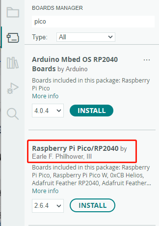
Click on Tools -> Dev Board -> Dev Board Manager -> Search for pico, it shows installed since my computer has already installed it.


Upload Demo At the First Time
-
Press and hold the BOOTSET button on the Pico board, connect the Pico to the USB port of the computer via the Micro USB cable, and release the button when the computer recognizes a removable hard drive (RPI-RP2).

- Download the demo, open arduino\PWM\D1-LED path under the D1-LED.ino.
-
Click Tools -> Port, remember the existing COM, do not need to click this COM (different computers show different COM, remember the existing COM on your computer).

-
Connect the driver board to the computer with a USB cable, then click Tools -> Ports, select uf2 Board for the first connection, and after the upload is complete, connecting again will result in an additional COM port.

-
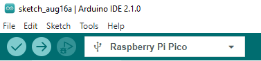
Click Tool -> Dev Board -> Raspberry Pi Pico/RP2040 -> Raspberry Pi Pico.

-
After setting, click the right arrow to upload.
- If you encounter problems during the period, you need to reinstall or replace the Arduino IDE version, uninstall the Arduino IDE needs to be uninstalled cleanly, after uninstalling the software you need to manually delete all the contents of the folder C:\Users\[name]\AppData\Local\Arduino15 (you need to show the hidden files in order to see it) and then reinstall.


Open Source Demo
- MicroPython Demo (GitHub)
- MicroPython Firmware/Blink Demo (C)
- Official Raspberry Pi C/C++ Demo
- Official Raspberry Pi MicroPython Demo
- Arduino Official C/C++ Demo
Support
Technical Support
If you need technical support or have any feedback/review, please click the Submit Now button to submit a ticket, Our support team will check and reply to you within 1 to 2 working days. Please be patient as we make every effort to help you to resolve the issue.
Working Time: 9 AM - 6 AM GMT+8 (Monday to Friday)