
ARPI600
| ||

Introduction
ARPI600 is an expansion board compatible with Raspberry Pi, Arduino and XBee, which can be used to expand common interface resources.
| More |
Feature
- Onboard USB to serial port (support Raspberry Pi serial port debugging), RTC and ADC etc.
- Support Arduino interface (with AD function), which is convenient for Raspberry Pi to connect to various Arduino expansion boards (Shield).
- Support Raspberry Pi for wireless data transmission through XBee communication module, and support XBee USB adapter function.
- Support sensor interface, convenient for Raspberry Pi to connect to various sensors.
Onboard Resources


How to use Raspberry Pi
Open I2C Interface
- Open the Raspberry Pi terminal and enter the following command to enter the configuration interface
sudo raspi-config
Choose Interfacing Options -> I2C ->yes Start the i2C kernel driver

Reboot Raspberry Pi
sudo reboot
User Guides for Raspberry Pi
Enable SPI Interface
PS: If you are using the system of the Bullseye branch, you need to change "apt-get" to "apt", the system of the Bullseye branch only supports Python3.
Open the Raspberry Pi terminal and enter the following command to enter the configuration interface
sudo raspi-config
Select Interfacing Options -> SPI -> Yes to enable the SPI interface

Reboot Raspberry Pi
sudo reboot
Please make sure the SPI is not occupied by other devices, you can check in the middle of /boot/config.txt
Enable Uart Interface
Open the Raspberry Pi terminal and enter the following command to enter the configuration interface
sudo raspi-config
Select Interfacing Options -> Serial, close the shell access, open the hardware serial port

Install Library Function
If you use bookworm system, only the lgpio library is available, bcm2835 and wiringPi libarary cannot be installed or used. Please note that the python library does not need to be installed, you can directly run the demo.
BCM2835
#Open the Raspberry Pi terminal and run the following commands:
sudo wget http://www.airspayce.com/mikem/bcm2835/bcm2835-1.71.tar.gz
sudo tar zxvf bcm2835-1.71.tar.gz
cd bcm2835-1.71/
sudo ./configure && sudo make && sudo make check && sudo make install
# For more information, please refer to the official website: http://www.airspayce.com/mikem/bcm2835/
wiringPi
#Open the Raspberry Pi terminal and run the following commands:
cd
sudo apt-get install wiringpi
#For Raspberry Pi systems after May 2019 (those earlier may not require execution), an upgrade may be necessary:
wget https://files.waveshare.com/wiki/common/wiringpi-latest.deb
sudo dpkg -i wiringpi-latest.deb
gpio -v
# Run gpio -v and version 2.52 will appear. If it does not appear, there is an installation error

#Bullseye branch system uses the following command:
sudo git clone https://github.com/WiringPi/WiringPi
cd WiringPi
sudo ./build
gpio -v
# Run gpio -v and version 2.70 will appear. If it does not appear, there is an installation error
lgpio
sudo su
wget https://github.com/joan2937/lg/archive/master.zip
unzip master.zip
cd lg-master
sudo make install
# For more information, please refer to the official website: https://github.com/gpiozero/lg
- python
sudo apt-get update
sudo apt-get install ttf-wqy-zenhei
sudo apt-get install python-pip
sudo pip install RPi.GPIO
sudo pip install spidev
sudo apt-get install python-smbus
sudo apt-get install python-serial
sudo pip install rpi_ws281x
Download Demo
sudo apt-get install p7zip
wget https://www.waveshare.com/wiki/File:ARPI600_.7z
7zr x ARPI600.7z -r -o./ARPI600
sudo chmod 777 -R ARPI600
cd ARPI600/RaspberryPi/program
Connecting Raspberry Pi UART to control peripherals
Configure the system serial port
1) Enter the terminal and execute:
sudo nano /boot/cmdline.txt
put the following line:
wc_otg.lpm_enable=0 console=ttyAMA0,115200 kgdboc=ttyAMA0,115200 console=tty1 root=/dev/mmcblk0p2 rootfstype=ext4 elevator=deadline rootwait
Change it to the following line:
dwc_otg.lpm_enable=0 console=tty1 root=/dev/mmcblk0p2 rootfstype=ext4
elevator=deadline rootwait
Press Ctrl+X and select Y to save. 2) Execute:
sudo nano /etc/inittab
find the following line:
#Spawn a getty on Raspberry Pi serial line
T0:23:respawn:/sbin/getty -L ttyAMA0 115200 vt100
change to
#Spawn a getty on Raspberry Pi serial line
#T0:23:respawn:/sbin/getty -L ttyAMA0 115200 vt100
Press Ctrl+X, select Y to save
3) Execute:
sudo reboot
After executing this command and restarting the Raspberry Pi, you will not be able to enter the Raspberry Pi terminal from the serial port. At this time, if the user wants to enter the terminal, he must use SSH or connect the Raspberry Pi to an external monitor and enter the LX terminal. (If you want the serial port to be used as the debug output of the Raspberry Pi serial port again, you can restart after restoring the changes, so it is best to back up before making changes)
Serial data display
1. Set the jumpers on the ARPI600: connect CP_RX to P_TX, and CP_TX to CP_RX.
2. Start the PuTTY serial debugging software to configure following parameters:
- Serial line: it is used to select corresponding serial port.
- Speed: it is used to set the Baud rate: 9600 (Notices: the parameter Speed in here is set to 9600, differently from the configuration shown in the figure).
- Connection type: this option should be set to Serial.
3. Copy the file program/Xbee/send into the Raspbian, and enter the folder send, then, execute the following code:
sudo make
sudo ./serialTest
The terminal will display the data as

Building a wireless network with two XBee modules
Preparations
- Two XBee modules
- Two ARPI600 modules
- Twp Raspberry Pi boards
- In this document, we will divide the device above into two groups: Group A and Group B(XBee-A, ARPI600-A, XBee-B, and ARPI600-B)
Installing X-CTU tool
- Double click the file software/X-CTU V5.2.8.6.exe on your PC to start installing X-CTU tool. After a successful installation, you can open the X-CTU tool as the figure shows.
- X-CTU setting
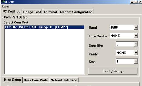
- Configure the XBee module. The default setting of XBee is as follows:
- Baud: 9600
- Data Bite: 8
- Parity: NONE
- Stop: 1

Testing the connection between PC and XBee
- Connect XBee-A to ARPI600-A, and XBee-B to ARPI600-B, respectively.
- Set the jumpers on ARPI600 to start up the serial debugging function for the XBee, as the figure shows.
- Connect XB_RX to CP_RX
- Connect CP_TX to XB_TX
- Jumpers setting for serial debugging function between the Pi and the XBee

- Power up Raspberry Pi board.
- Click the button Test/Query to check whether the connection between the ARPI600 and the XBee is established successfully.
- For a successful connection, you can see the dialog box as the figure shows.
- Successful connection


Configuring XBee-A module
- Select the option Modem Configuration, and click the button Read to read out the current parameters of XBee.
- Reading out current parameters

- Select the option ZIBGEE ROUTER/END DEVICE AT under the pull-down menu Function Set:
- Selecting the option ZIBGEE ROUTER/END DEVICE AT under Function Set

- Set the read Networking parameters:
- ID: 234
- DH: 0
- DL: 0
- Click the button Write to download the configured parameters into the XBee-A module

Configuring XBee-B module
- Configure the XBee-B module according to the processes described in the Section 3.1 and the Section 0. However, there is something different. In configuring XBee-B, you should select the option ZIBGEE COORDINATOR AT under the pull-down menu Function Set:
- Selecting the option ZIBGEE COORDINATOR AT under Function Set

- Set the read Networking parameters:
- ID: 234
- DH: 0
- DL: ffff
- Click the button Write to download the configured parameters into the XBee-B module.
- To implement a simple P2P network, please configure XBee-A and XBee-B according to the processes described above. Start two X-CTU tools, and select different COM interfaces in the option PC Settings to control Group A and Group B respectively.
- Input the data to be transmitted in the X-CTU Terminal of XBee-A, then, you can find that the inputted data will be sent to XBee-B automatically, and displayed in the X-CTU Terminal of XBee-B. In the X-CTU, data in blue is the data to be sent, and data in red is the received data.
- Data transmission and receive

- This Figure shows the normal operating state of the XBee module.


Raspberry Pi transmits data wirelessly via XBee
After making sure that the wireless transmission network of 2 XBee is normal, now the Raspberry Pi can transmit data wirelessly through XBee.
1) Set the ARPI600 jumper:
Connect the two Raspberry Pi serial ports for sending and receiving to the XBee serial port, and the ARPI600 expansion board jumpers according to the red frame in the figure below.
- XB_RX connects to P_TX
- XB_TX connects to P_RX

2) Test the Raspberry Pi serial port:
Execute:
cd /Xbee/getdata
sudo make
sudo ./serialTest
The serial terminal prints out the following
![]()
Run the sender code again, copy program/Xbee/send to the sender Raspberry Pi system, enter the send folder, and execute.
sudo make sudo ./serialTest Then the receiver will print the received data:

RTC clock
- Set the jumpers on RTC JMP of the ARPI600.
- Open the LXTerminal on the desktop of Raspbian, and input the code:
i2cdetect -y 1
- Then, you will see the device address of PCF8563 connected to Raspberry Pi. Here, the device address of PCF8563 is 51, which means the PCF8563 is identified by Raspberry Pi.
- The device address of PCF8563 connected to Raspberry Pi

- Enter LXTerminal, and run:

modprobe i2c-dev
echo pcf8563 0x51 > /sys/class/i2c-adapter/i2c-1/new_device
hwclock -r# (time to read the connected I2C hardware RTC)
LXTerminal will print out the PCF8563 time, which is different from the system time.
- Execute in LXTerminal
hwclock -w # (write the time of the Raspberry Pi system to PCF8563)
hwclock -r # (The time of the Raspberry Pi system is synchronized to the PCF8563)
hwclock -s # (set the system time to synchronize with the hardware's RCT clock)
AD conversion (ARPI600 on-board chip TLC1543)
Configuring Pin A0 to Pin AD
- Please make sure you have installed relative libraries (refer to the Section 2.2: Installing relative libraries).
- Set the jumpers to select reference voltage:
- Connect REF to 5V, which means the AD conversion reference voltage is 5V (connecting to 5V is a default setting).
- Connect REF to 3V3, which means the AD conversion reference voltage is 3.3V.
- Notices: REF can only be connected to one reference voltage at a time.
- Setting AD reference voltage

- Copy the file program/AD_TLC1543 in to Raspbian. Then, enter the folder AD_TLC1543, and execute the following code under the terminal:
sudo make
sudo ./tlc1543
- Terminal will display relative AD conversion value. By default, the displayed conversion value comes from Pin AD0 on TLC1543 (Pin T_A0 on ARPI600).
- Connect the jumpers T_A0 to A0, then the Pin A0 on the Arduino interface can serve as an AD conversion pin, as shown.
- connecting Pin T_A0 to Pin A0


Configuring as other AD pins
- If you want to display the conversion value from other AD pins on TLC1543, please enter the terminal and edit the file tlc1543.c:
sudo nano tlc1543.c
- Find out the following line:
re=ADCSelChannel(0);
- Modify the "0" in the line into the number corresponding to the other AD pins (For example, modify to "1" for testing the conversion value from Pin AD1 (Pin T_A1), and modify to "2" for testing the conversion value from Pin AD2 (Pin T_A2), and so on, until to "10" for testing the conversion value from Pin AD10 (T_A10)).
- After completing the operation described above, press the keys Ctrl+X, and select the option Y to save the modification.
- Find out the following line:
- Execute the following code under the terminal:
sudo make
sudo ./tlc1543
- Now, the modification is in effect.
Interface description
Interface overview
The default relationship between Arduino digital control pins and Raspberry Pi IOs is shown in the table. The relationship between Arduino digital control pins and Raspberry Pi IOs
| APRI600 | IO of Raspberry Pi B+ |
|---|---|
| D0 | P_RX |
| D1 | P_TX |
| D2 | P0 |
| D3 | P1 |
| D4 | P2 |
| D5 | P3 |
| D6 | P4 |
| D7 | P5 |
| D8 | P6 |
| D9 | P7 |
| D10 | CE0 |
| D11 | MOSI |
| D12 | MISO |
| D13 | SCK |
The jumper pins D11, D12 and D13 on the module are used for configuring the ARPI600. And these pins should be shorted by the 0Ω resistances.
- Configuring the jumpers D11, D12 and D13


In factory settings, the jumpers are set as follows:
- Connect SCK to D13
- Connect MISO to D12
- Connect MOSI to D11
The following settings are connecting pins D11, D12, and D13 to the general IO control pins of the Raspberry Pi board.
- Connect D13 to P26
- Connect D12 to IO_SD
- Connect D11 to IO_SC
Notices: Users can modify the settings of these jumpers as required. In this operation, welding is required. Any changes under no guidance from Waveshare will be considered as a waiver of warranty.
The pins A0-A5 of ARPI600 can also be configured as IO pins or ADC pins.
- configuring Pins A0-A5


a) When the pins A0-A5 are connected to 1, they will sever as IO control pins. The relationship between the pins A0-A5 and the pins of the Raspberry Pi board is as the table shows.
- The relationship between the pins A0-A5 and the pins of the Raspberry Pi board
| APRI600 | IO of Raspberry Pi B+ |
|---|---|
| A0 | CE1 |
| A1 | P5 |
| A2 | P6 |
| A3 | P7 |
| A4 | CW0 |
| A5 | MOSI |
b) When the pins A0-A5 are connected to 3, they will sever as ADC pins.
You can also connect the pin A4 to P_SCL, and the pin A5 to P_SDA (as the figure shows), to make them serve as I2C control pins of the Raspberry Pi board. However, in default settings, the pins A4 and P_SCL are disconnected, and so are the pins A5 and P_SDA.
Notices: Users can modify the settings of these jumpers as required. In this operation, welding is required. Any changes under no guidance from Waveshare will be considered as a waiver of warranty.
- Setting the pins A4 and A5 as I2C control pins


ARPI600 provides sensor interfaces 4P. The figure shows the jumper settings for sensor interface 4P.
- Sensor interface 4P


In which:
- The pins on A are connected to the ADC pins A6-A10 of TLC1543;
- The pins on D are connected to the IO control pins P0-P4 of the Raspberry Pi board.
Users can apply different sensors via the sensor interface.
How to use ARPI600 with external sensor kits (purchased separately)
The following operations require the ARPI600 to be plugged into the Raspberry Pi. If there is only ARPI600 and sensor kit, but no Raspberry Pi, it will not work.
Color Sensor
1) Insert the ARPI600 into the Raspberry Pi.
2) Connect the sensor and ARPI600 pins according to the following table:
| Color Sensor Pins | ARPI600 Pins |
|---|---|
| LED | 3.3V |
| OUT | P0 |
| S3 | P4 |
| S2 | P3 |
| S1 | P2 |
| S0 | P1 |
| GND | GND |
| VCC | 3.3V |
- Copy the folder Color_Sensor into the Raspberry Pi system, and then power up the device. Enter the terminal and run the following commands:
cd Color_Sensor
sudo ./Color_Sensor
- The program performs the white balance adjustment to the sensor and it may take 2 seconds. When finished, you can see relative data of RGB are outputted on the terminal. A color check list is helpful for finding out what the measured color it is.
- Press the keys Ctrl+C to end the program.
Flame Sensor
- Install the ARPI600 to the RPi board;
- Connect the sensor to the corresponding pins on the ARPI600, according to the following table:
| Flame Sensor Pins | ARPI600 Pins |
|---|---|
| DOUT | P0 |
| AOUT | T_A6 |
| GND | GND |
| VCC | 3.3V |
- Copy the folder Flame_Sensor into the Raspberry Pi system, and then power up the device. Enter the terminal and run the following commands:
cd Flame_Sensor
sudo ./General_Sensor
- The signal indicator will turn on, when the sensor is close to a fire. And it will turn off, when the sensor is away from the fire.
- The terminal output changes along with the distance from the sensor to the fire.
- Press the keys Ctrl+C to end the program.
Notice: The flame sensor is designed to detect fire only, but it is not fireproof itself. When using it, please keep a safe distance from the fire to avoid burning out.
Metal Sensor
Plug the ARPI600 into the Raspberry Pi. 2) Connect the sensor and ARPI600 pins according to the following table:
| Metal Sensor Pins | ARPI600 Pins |
|---|---|
| DOUT | P0 |
| AOUT | T_A6 |
| GND | GND |
| VCC | 3.3V |
3) Copy the Metal_Sensor folder to the Raspberry Pi system. After power on, the terminal executes:
cd Metal_Sensor
sudo ./General_Sensor
4) When the sensor touches live metal, the signal indicator on the module lights up. When the sensor is away from the metal, the signal indicator on the module goes out.
5) As the sensor contacts and separates from the metal, the data output by the terminal will change accordingly.
6) Press Ctrl+C to end the program.
Hall Sensor
- Install the ARPI600 to the RPi board;
- Connect the sensor to the corresponding pins on the ARPI600, according to the following table:
| Hall Sensor Pins | ARPI600 Pins |
|---|---|
| DOUT | P0 |
| AOUT | T_A6 |
| GND | GND |
| VCC | 3.3V |
- Copy the folder Hall Sensor into the Raspberry Pi system, and then power up the device. Enter the terminal and run the following commands:
cd Hall_Sensor
sudo ./General_Sensor
- The signal indicator will turn on, when the sensor is close to a magnet. And it will turn off, when the sensor is away from the magnet.
- The terminal output changes along with the distance from the sensor to the magnet.
- Press the keys Ctrl+C to end the program.
Infrared Reflective Sensor
- Install the ARPI600 to the RPi board;
- Connect the sensor to the corresponding pins on the ARPI600, according to the following table:
| Infrared Reflective Sensor Pins | ARPI600 Pins |
|---|---|
| DOUT | P0 |
| AOUT | T_A6 |
| GND | GND |
| VCC | 3.3V |
- Copy the folder Infrared_Reflective_Sensor into the Raspberry Pi system, and then power up the device. Enter the terminal and run the following commands:
cd Infrared_Reflective_Sensor
sudo ./General_Sensor
- The signal indicator will turn on, when the sensor is close to a barrier. And it will turn off, when the sensor is away from the barrier.
- The terminal output changes along with the distance from the sensor to the barrier.
- Press the keys Ctrl+C to end the program.
Laser Sensor
- Install the ARPI600 to the RPi board;
- Connect the sensor to the corresponding pins on the ARPI600, according to the following table:
| Laser Sensor Pins | ARPI600 Pins |
|---|---|
| DOUT | P0 |
| GND | GND |
| VCC | 3.3V |
- Copy the folder Laser_Sensor into the Raspberry Pi system, and then power up the device. Enter the terminal and run the following commands:
cd Laser_Sensor
sudo ./General_Sensor
- The signal indicator will turn on, when a barrier is placed above the sensor. And the signal indicator will turn off, when the barrier is away from the sensor. By reading the status of the indicator, you can get to know whether the sensor has detected the barrier.
- Press the keys Ctrl+C to end the program.
Moisture Sensor
- Install the ARPI600 to the RPi board;
- Connect the sensor to the corresponding pins on the ARPI600, according to the following table:
| Moisture Sensor Pins | ARPI600 Pins |
|---|---|
| DOUT | P0 |
| AOUT | T_A6 |
| GND | GND |
| VCC | 3.3V |
- Copy the folder Moisture_Sensor into the Raspberry Pi system, and then power up the device. Enter the terminal and run the following commands:
cd Moisture_Sensor
sudo ./General_Sensor
- Insert the sensor into the soil and water the soil little by little. And then you may find the terminal output changes.
- Press the keys Ctrl+C to end the program.
Rotation Sensor
- Install the ARPI600 to the RPi board;
- Connect the sensor to the corresponding pins on the ARPI600, according to the following table:
| Rotation Sensor Pins | ARPI600 Pins |
|---|---|
| SIA | P0 |
| SIB | P1 |
| SW | P2 |
| GND | GND |
| VCC | 3.3V |
- Copy the folder Rotation_Sensor into the Raspberry Pi system, and then power up the device. Enter the terminal and run the following commands:
cd Rotation_Sensor
sudo ./Rotation_Sensor
- There are three actions of the rotary encoder: clockwise rotation, anticlockwise rotation, and reset button press. The terminal output of the module varies with different actions.
- Turn right!
- Turn left!
- Turn down!
- Connect the SIA, SIB, and SW of the module to CH0, CH1, and CH2 of a logic analyzer (purchased separately), respectively.
- For clockwise rotation, the waveform outputs are shown as below:

- For anticlockwise rotation, the waveform outputs are shown as below:

- When the reset button is pressed, the waveform outputs are shown below:

- Press the keys Ctrl+C to end the program.
Sound Sensor
- Install the ARPI600 to the RPi board;
- Connect the sensor to the corresponding pins on the ARPI600, according to the following table:
| Sound Sensor Pins | ARPI600 Pins |
|---|---|
| DOUT | P0 |
| AOUT | T_A6 |
| GND | GND |
| VCC | 3.3V |
- Copy the folder Sound_Sensor into the Raspberry Pi system, and then power up the device. Enter the terminal and run the following commands:
cd Sound_Sensor
sudo ./General_Sensor
- The signal indicator will turn on, when the microphone of the module is close to a sound source. And it will turn off, when the microphone is away from the magnet.
- The terminal output changes along with the distance from the sensor to the sound source.
- Press the keys Ctrl+C to end the program.
Temperature-Humidity Sensor
- Install the ARPI600 to the RPi board;
- Connect the sensor to the corresponding pins on the ARPI600, according to the following table:
| Temperature-Humidity Sensor Pins | ARPI600 Pins |
|---|---|
| DOUT | P0 |
| GND | GND |
| VCC | 3.3V |
- Copy the folder Temperature-Humidity_Sensor into the Raspberry Pi system, and then power up the device. Enter the terminal and run the following commands:
cd Temperature-Humidity_Sensor
sudo ./DHT11
- The data of temperature and humidity detected are shown on the terminal. For example:
- Humidity=33
- Temperature=28
- Press the keys Ctrl+C to end the program.
MQ-5 Gas Sensor
- Install the ARPI600 to the RPi board;
- Connect the sensor to the corresponding pins on the ARPI600, according to the following table:
| MQ-5 Gas Sensor Pins | ARPI600 Pins |
|---|---|
| DOUT | P0 |
| AOUT | T_A6 |
| GND | GND |
| VCC | 3.3V |
- Copy the folder MQ-5_Gas_Sensor into the Raspberry Pi system, and then power up the device. Enter the terminal and run the following commands:
cd MQ-5_Gas_Sensor
sudo ./General_Sensor
- Warn-up the sensor for a minute.
- Put the sensor into a container filled with sensitive gas, you will find the indicator turns on. While taking the sensor out of the container, you can see the indicator turns off. By reading the indicator, you can get to know whether the concentration of the sensitive gas exceeds standard.
- Press the keys Ctrl+C to end the program.
Tilt Sensor
- Install the ARPI600 to the RPi board;
- Connect the sensor to the corresponding pins on the ARPI600, according to the following table:
| Tilt Sensor Pins | ARPI600 Pins |
|---|---|
| DOUT | T_A6 |
| GND | GND |
| VCC | 3.3V |
- Copy the folder Tilt_Sensor into the Raspberry Pi system, and then power up the device. Enter the terminal and run the following commands:
cd Tilt_Sensor
sudo ./General_Sensor
- The signal indicator will turn on, when the sensor is being vibrated or in a tilted state. And it will turn off, when the sensor is laid flat. By reading the indicator, you can get to know whether the module is in a condition of vibrating or tilting.
- Press the keys Ctrl+C to end the program.
UV Sensor
- Install the ARPI600 to the RPi board;
- Connect the sensor to the corresponding pins on the ARPI600, according to the following table::
| UV Sensor Pins | ARPI600 Pins |
|---|---|
| AOUT | T_A6 |
| GND | GND |
| VCC | 3.3V |
- Copy the folder UV_Sensor into the Raspberry Pi system, and then power up the device. Enter the terminal and run the following commands:
cd UV_Sensor
sudo ./General_Sensor
- Place the sensor close to the sunlight. The terminal output changes along with the distance from the sensor to the sunlight source.
- Press the keys Ctrl+C to end the program.
Liquid Level Sensor
- Install the ARPI600 to the RPi board;
- Connect the sensor to the corresponding pins on the ARPI600, according to the following table:
| Liquid Level Sensor Pins | ARPI600 Pins |
|---|---|
| AOUT | T_A6 |
| GND | GND |
| VCC | 3.3V |
- Copy the folder Liquid_Level_Sensor into the Raspberry Pi system, and then power up the device. Enter the terminal and run the following commands:
cd Liquid_Level_Sensor
sudo ./General_Sensor
- Immerse the sensor into the water deeply. The terminal output changes along with the water depth.
- Press the keys Ctrl+C to end the program.
Jetson Nano
Jetson nano provides some demos for use, and others are not currently supported.
Install Library Function
- Open the terminal interface and enter the following command to install the corresponding library function:
sudo apt-get update
sudo apt-get install python3-pip
sudo pip3 install Jetson.GPIO
sudo groupadd -f -r gpio
sudo usermod -a -G gpio your_user_name
sudo cp /opt/nvidia/jetson-gpio/etc/99-gpio.rules /etc/udev/rules.d/
sudo udevadm control --reload-rules && sudo udevadm trigger
[Note] your_user_name is the username you use, such as waveshare.
- Install I2C
sudo apt-get install python-smbu
- Install Image Processing Libraries
sudo apt-get install python3-pil
sudo apt-get install python3-numpy
Download Demo
sudo apt-get install p7zip
wget http://www.waveshare.net/w/upload/3/37/ARPI600.7z
7zr x ARPI600.7z -r -o./ARPI600
sudo chmod 777 -R ARPI600
cd ARPI600/JetsonNano/ARPI600_Code
Demo
PCF8563
cd PCF8563
- C
cd C
make clear
make
sudo ./main
- python2
cd python2
sudo python main.py
- python3
cd python3
sudo python3 main.py
TLC1543
cd TLC1543
- C
cd C
make clear
make
sudo ./main
- python2
cd python2
sudo python main.py
- python3
cd python3
sudo python3 main.py
UART
cd UART
- C
cd C
make clear
make
sudo ./main
- python2
cd python2
sudo python main.py
- python3
cd python3
sudo python3 main.py
Resources
Document
Application Notes
Datasheets
Software
Support
Technical Support
If you need technical support or have any feedback/review, please click the Submit Now button to submit a ticket, Our support team will check and reply to you within 1 to 2 working days. Please be patient as we make every effort to help you to resolve the issue.
Working Time: 9 AM - 6 PM GMT+8 (Monday to Friday)